6.5 Alarm Detection
278 YASKAWA ELECTRIC SIEP C710616 35D YASKAWA AC Drive E1000 Technical Manual
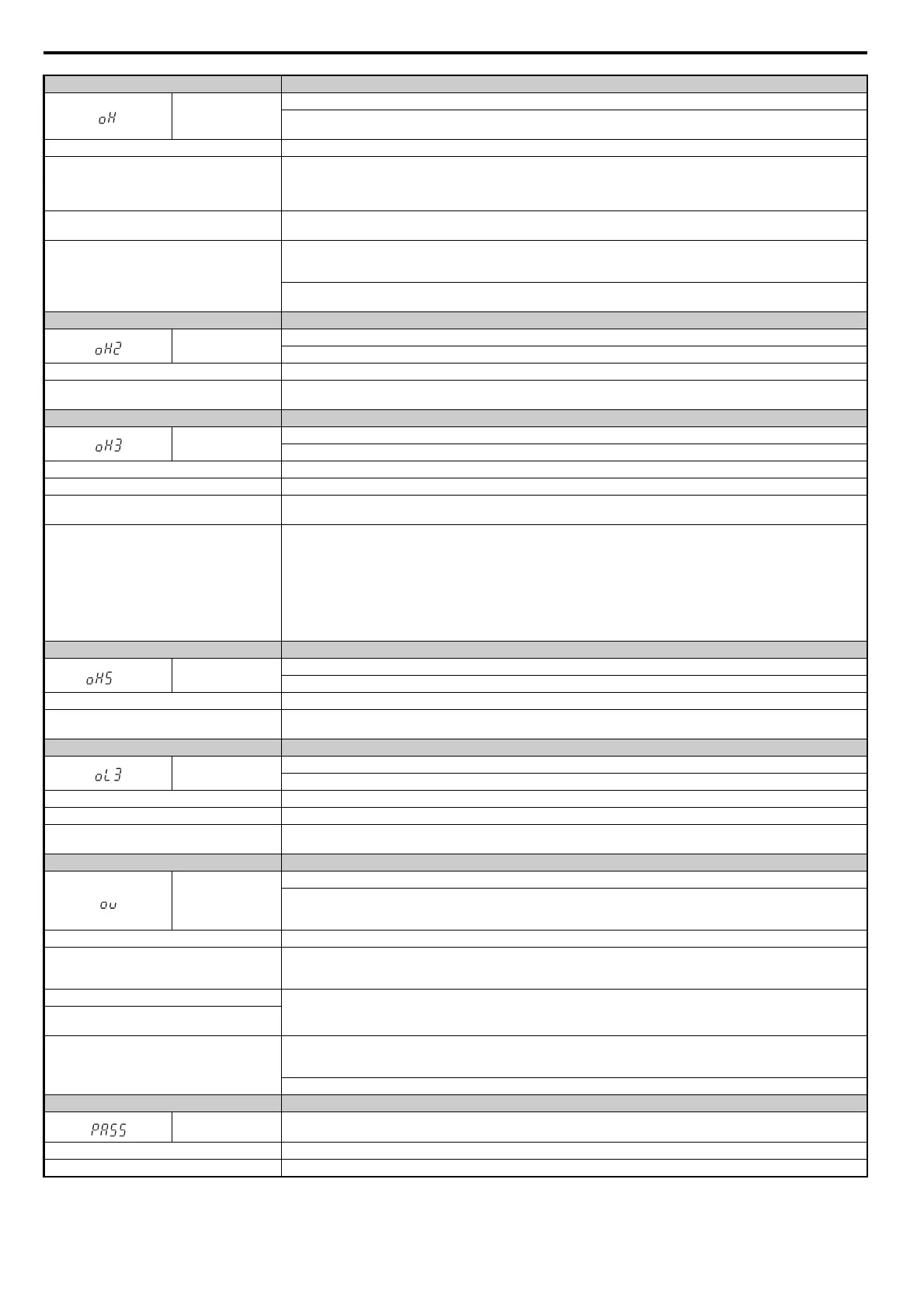
Digital Operator Display Minor Fault Name
oH
Heatsink Overheat
The temperature of the heatsink exceeded the overheat pre-alarm level set to L8-02 (90-100°C). Default value for L8-02 is
determined by drive capacity (o2-04).
Cause Possible Solutions
Surrounding temperature is too high
• Check the surrounding temperature.
• Improve the air circulation within the enclosure panel.
• Install a fan or air conditioner to cool surrounding area.
• Remove anything near drive that may cause extra heat.
Internal cooling fan has stopped.
• Replace the cooling fan. Refer to Cooling Fan Component Names on page 303.
• After replacing the drive, reset the cooling fan maintenance parameter to (o4-03 = “0”).
Airflow around the drive is restricted.
• Provide proper installation space around the drive as indicated in the manual. Refer to Installation Orientation and Spacing on
page 44.
• Allow for the specified space and ensure that there is sufficient circulation around the control panel.
• Check for dust or foreign materials clogging cooling fan.
• Clear debris caught in the fan that restricts air circulation.
Digital Operator Display Minor Fault Name
oH2
Drive Overheat Alarm
“Drive Overheat Alarm” was input to a multi-function input terminal, S1 through S8 (H1-= B)
Cause Possible Solutions
An external device triggered an overheat Alarm in
the drive.
• Search for the device that tripped the overheat warning.
• Solving the problem will clear the warning.
Digital Operator Display Minor Fault Name
oH3
Motor Overheat
The motor overheat signal entered to a multi-function analog input terminal exceeded the alarm level (H3-02, H3-06 or H3-10 = E).
Cause Possible Solutions
Motor thermostat wiring is fault (PTC input). Repair the PTC input wiring.
There is a fault on the machine side (e.g., the
machine is locked up).
• Check the status of the machine.
• Remove the cause of the fault.
Motor has overheated.
• Check the load size, accel/decel times, and cycle times.
• Decrease the load.
• Increase accel and decel times (C1-01 to C1-04).
• Adjust the preset V/f pattern (E1-04 through E1-10). This will mainly involve reducing E1-08 and E1-10.
Note: Do not lower E1-08 and E1-10 excessively, because this reduces load tolerance at low speeds.
• Check the motor-rated current.
• Enter motor-rated current on motor nameplate (E2-01).
• Ensure the motor cooling system is operating normally.
• Repair or replace the motor cooling system.
Digital Operator Display Minor Fault Name
<1>
oH5
Motor Overheat (NTC Input)
The motor temperature exceeded the level set in L1-16.
Cause Possible Solution
Motor has overheated.
• Reduce the load.
• Check the ambient temperature.
Digital Operator Display Minor Fault Name
oL3
Overtorque 1
Drive output current was greater than L6-02 for longer than the time set in L6-03.
Cause Possible Solutions
Inappropriate parameter settings. Check parameters L6-02 and L6-03.
There is a fault on the machine side (e.g., the
machine is locked up).
• Check the status of the machine.
• Remove the cause of the fault.
Digital Operator Display Minor Fault Name
ov
DC Bus Overvoltage
The DC bus voltage exceeded the trip point.
For 200 V class: approximately 410 V
For 400 V class: approximately 820 V
Cause Possible Solutions
Surge voltage present in the drive input power.
• Install a DC reactor or an AC reactor.
• Voltage surge can result from a thyristor convertor and a phase advancing capacitor operating on the same drive input power
system.
The motor is short-circuited.
• Check the motor power cable, relay terminals and motor terminal box for short circuits.
• Correct grounding shorts and turn the power back on.
Ground current has over-charged the main circuit
capacitors via the drive input power.
Noise interference causes the drive to operate
incorrectly.
• Review possible solutions for handling noise interference.
• Review section on handling noise interference and check control circuit lines, main circuit lines and ground wiring.
• If the magnetic contactor is identified as a source of noise, install a surge protector to the MC coil.
Set number of fault restarts (L5-01) to a value other than 0.
Digital Operator Display Minor Fault Name
PASS
MEMOBUS/Modbus Comm. Test Mode Complete
Cause Possible Solutions
MEMOBUS/Modbus test has finished normally. This verifies that the test was successful.
SIEP_C710616_35.book 278 ページ 2015年11月30日 月曜日 午後2時2分
 Loading...


