B.6 Defaults by Drive Model Selection (o2-04)
YASKAWA ELECTRIC SIEP C710616 35D YASKAWA AC Drive E1000 Technical Manual 401
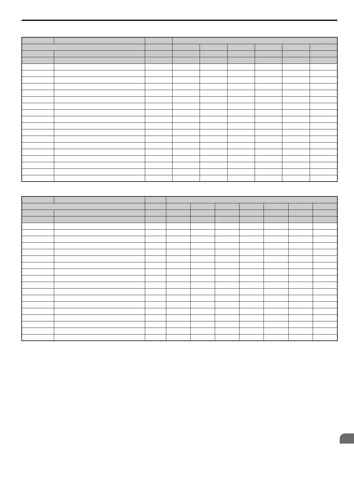
Table B.7 400 V Class Drives Default Settings by Drive Capacity
No. Name Unit Default Settings
Model CIMR-E – 2A0169 2A0211 2A0250 2A0312 2A0360 2A0415
o2-04 Drive Model Selection Hex. 73 74 75 76 77 78
E2-11 Motor rated Output kW 45 55 75 90 110 110
b3-04 V/f Gain during Speed Search % 80 80 80 80 80 80
b3-06 Output Current 1 during Speed Search – 0.5 0.5 0.7 0.7 0.7 0.7
b8-04 Energy Saving Coefficient Value – 35.78 31.35 23.1 20.65 18.12 18.12
C6-02 Carrier Frequency Selection – 7 7 7 7 7 7
E2-01 Motor Rated Current A 160 190 260 260 260 260
E2-02 Motor Rated Slip Hz 1.6 1.43 1.39 1.39 1.39 1.39
E2-03 Motor No-Load Current A 44 45.6 72 72 72 72
E2-05 Motor Line to Line Resistance Ω 0.03 0.022 0.023 0.023 0.023 0.023
E2-06 Motor Leakage Inductance % 20.2 20.5 20 20 20 20
E2-10 Motor Iron Loss for Torque Compensation W 852 960 1200 1200 1200 1200
E5-01 Motor Code Selection Hex. 1213 1214 1215 1216 FFFF FFFF
L2-02 Momentary Power Loss Ride-Thru Time s 2 2 2 2 2 2
L2-03 Momentary Power Loss Minimum Baseblock Time s 1.2 1.3 1.5 1.5 1.7 1.7
L2-04 Momentary Power Loss Voltage Recovery Time s 1 1 1 1 1 1
L3-24 Motor Acceleration Time for Inertia Calculations s 0.387 0.317 0.533 0.592 0.646 0.646
L8-02 Overheat Alarm Level °C 130 125 115 120 120 120
L8-35 Installation Method Selection – 0 0 0 0 0 0
n1-03 Hunting Prevention Time Constant ms 10 10 10 10 100 100
No. Name Unit Default Settings
Model CIMR-E – 4A0002 4A0004 4A0005 4A0007 4A0009 4A0011 4A0018
o2-04 Drive Model Selection Hex. 92 93 94 95 96 97 99
E2-11 Motor rated Output kW 0.75 1.5 2.2 3.0 3.7 5.5 7.5
b3-04 V/f Gain during Speed Search % 100 100 100 100 100 100 100
b3-06 Output Current 1 during Speed Search – 0.5 0.5 0.5 0.5 0.5 0.5 0.5
b8-04 Energy Saving Coefficient Value – 447.4 338.8 313.6 265.7 245.8 189.5 145.38
C6-02Carrier Frequency Selection –7777777
E2-01 Motor Rated Current A 1.6 3.1 4.2 5.7 7 9.8 13.3
E2-02 Motor Rated Slip Hz 2.6 2.5 3 2.7 2.7 1.5 1.3
E2-03 Motor No-Load Current A 0.8 1.4 1.5 1.9 2.3 2.6 4
E2-05 Motor Line to Line Resistance Ω 22.459 10.1 6.495 4.360 3.333 1.595 1.152
E2-06 Motor Leakage Inductance % 14.3 18.3 18.7 19 19.3 18.2 15.5
E2-10 Motor Iron Loss for Torque Compensation W 26 53 77 105 130 193 263
E5-01 Motor Code Selection Hex. 1232 1233 1235 1236 FFFF 1238 123A
L2-02 Momentary Power Loss Ride-Thru Time s 0.1 0.2 0.3 0.5 0.5 0.5 0.8
L2-03 Momentary Power Loss Minimum Baseblock Time s 0.3 0.4 0.5 0.5 0.6 0.7 0.8
L2-04 Momentary Power Loss Voltage Recovery Time s 0.3 0.3 0.3 0.3 0.3 0.3 0.3
L3-24 Motor Acceleration Time for Inertia Calculations s 0.142 0.166 0.145 0.145 0.154 0.168 0.175
L8-02 Overheat Alarm Level °C 110 110 110 110 110 110 110
L8-35Installation Method Selection –2222222
n1-03 Hunting Prevention Time Constant ms 10 10 10 10 10 10 10
SIEP_C710616_35.book 401 ページ 2015年11月30日 月曜日 午後2時2分