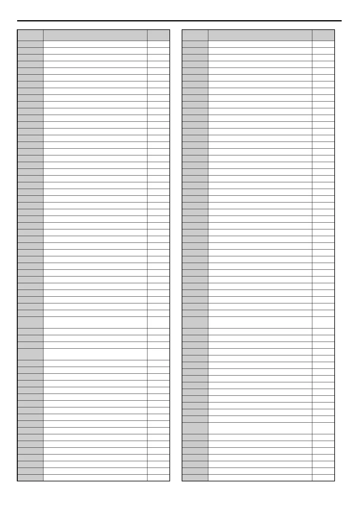
E.3 User Setting Table
466 YASKAWA ELECTRIC SIEP C710616 35D YASKAWA AC Drive E1000 Technical Manual
H5-07 RTS Control Selection
H5-09 CE Detection Time
H5-10 Unit Selection for MEMOBUS/Modbus Register 0025H
H5-11 Communications ENTER Function Selection
H5-12 Run Command Method Selection
H6-01 Pulse Train Input Terminal RP Function Selection
H6-02 Pulse Train Input Scaling
H6-03 Pulse Train Input Gain
H6-04 Pulse Train Input Bias
H6-05 Pulse Train Input Filter Time
H6-06 Pulse Train Monitor Selection
H6-07 Pulse Train Monitor Scaling
H6-08 Pulse Train Input Minimum Frequency
L1-01 Motor Overload Protection Selection
L1-02 Motor Overload Protection Time
L1-03 Motor Overheat Alarm Operation Selection (PTC input)
L1-04 Motor Overheat Fault Operation Selection (PTC input)
L1-05 Motor Temperature Input Filter Time (PTC input)
L1-13 Continuous Electrothermal Operation Selection
L1-15 Motor 1 Thermistor Selection (NTC)
L1-16 Motor 1 Overheat Temperature
L1-19 Operation at Thermistor Disconnect (THo) (NTC)
L1-20 Operation at Motor Overheat (oH5)
L2-01 Momentary Power Loss Operation Selection
L2-02 Momentary Power Loss Ride-Thru Time
L2-03 Momentary Power Loss Minimum Baseblock Time
L2-04 Momentary Power Loss Voltage Recovery Ramp Time
L2-05 Undervoltage Detection Level (Uv1)
L2-06 KEB Deceleration Time
L2-07 KEB Acceleration Time
L2-08 Frequency Gain at KEB Start
L2-10 KEB Detection Time
L2-11 DC Bus Voltage Setpoint During KEB
L2-29 KEB Method Selection
L3-01 Stall Prevention Selection during Acceleration
L3-02 Stall Prevention Level during Acceleration
L3-03 Stall Prevention Limit during Acceleration
L3-04 Stall Prevention Selection during Deceleration
L3-05 Stall Prevention Selection during Run
L3-06 Stall Prevention Level during Run
L3-11 Overvoltage Suppression Function Selection
L3-17
Target DC Bus Voltage for Overvoltage Suppression and
Stall Prevention
L3-20 DC Bus Voltage Adjustment Gain
L3-21 Accel/Decel Rate Calculation Gain
L3-22 Deceleration Time at Stall Prevention during Acceleration
L3-23
Automatic Reduction Selection for Stall Prevention during
Run
L3-24 Motor Acceleration Time for Inertia Calculations
L3-25 Load Inertia Ratio
L3-26 Additional DC Bus Capacitors
L3-27 Stall Prevention Detection Time
L4-01 Speed Agreement Detection Level
L4-02 Speed Agreement Detection Width
L4-03 Speed Agreement Detection Level (+/-)
L4-04 Speed Agreement Detection Width (+/-)
L4-05 Frequency Reference Loss Detection Selection
L4-06 Frequency Reference at Reference Loss
L4-07 Speed Agreement Detection Selection
L5-01 Number of Auto Restart Attempts
L5-02 Auto Restart Fault Output Operation Selection
L5-04 Fault Reset Interval Time
L5-05 Fault Reset Operation Selection
L6-01 Torque Detection Selection
L6-02 Torque Detection Level
L6-03 Torque Detection Time
No. Name
User
Setting
L6-13 Motor Underload Protection Selection
L6-14 Motor Underload Protection Level at Minimum Frequency
L8-02 Overheat Alarm Level
L8-03 Overheat Pre-Alarm Operation Selection
L8-05 Input Phase Loss Protection Selection
L8-06 Input Phase Detection Level
L8-07 Output Phase Loss Protection
L8-09 Output Ground Fault Detection Selection
L8-10 Heatsink Cooling Fan Operation Selection
L8-11 Heatsink Cooling Fan Off Delay Time
L8-12 Ambient Temperature Setting
L8-15 oL2 Characteristics Selection at Low Speeds
L8-18 Software Current Limit Selection
L8-19 Frequency Reduction Rate during Overheat Pre-Alarm
L8-27 Overcurrent Detection Gain
L8-29 Current Unbalance Detection (LF2)
L8-32 Current Unbalance Detection Current Level
L8-35 Installation Method Selection
L8-38 Carrier Frequency Reduction Selection
L8-40 Carrier Frequency Reduction Off Delay Time
L8-41 High Current Alarm Selection
L8-78 Power Unit Output Phase Loss Protection
n1-01 Hunting Prevention Selection
n1-02 Hunting Prevention Gain Setting
n1-03 Hunting Prevention Time Constant
n1-05 Hunting Prevention Gain while in Reverse
n3-01 High Slip Braking Deceleration Frequency Width
n3-02 High Slip Braking Current Limit
n3-03 High Slip Braking Dwell Time at Stop
n3-04 High Slip Braking Overload Time
n3-13 Overexcitation Deceleration Gain
n3-21 High-Slip Suppression Current Level
n3-23 Overexcitation Operation Selection
n8-45 Speed Feedback Detection Control Gain
n8-47 Pull-In Current Compensation Time Constant
n8-48 Pull-In Current
n8-49 d-Axis Current for High Efficiency Control
n8-51 Acceleration/Deceleration Pull-In Current
n8-54 Voltage Error Compensation Time Constant
n8-55 Load Inertia
n8-62 Output Voltage Limit
n8-65
Speed Feedback Detection Control Gain during ov
Suppression
o1-01 Drive Mode Unit Monitor Selection
o1-02 User Monitor Selection After Power Up
o1-03 Digital Operator Display Selection
o1-05 LCD Contrast Control
o1-06 User Monitor Selection Mode
o1-07 Second Line Monitor Selection
o1-08 Third Line Monitor Selection
o1-10 User-Set Display Units Maximum Value
o1-11 User-Set Display Units Decimal Display
o2-01 LO/RE Key Function Selection
o2-02 STOP Key Function Selection
o2-03 User Parameter Default Value
o2-04 Drive Model Selection
o2-05 Frequency Reference Setting Method Selection
o2-06
Operation Selection when Digital Operator is
Disconnected
o2-07 Motor Direction at Power Up when Using Operator
o3-01 Copy Function Selection
o3-02 Copy Allowed Selection
o4-01 Cumulative Operation Time Setting
o4-02 Cumulative Operation Time Selection
o4-03 Cooling Fan Maintenance Operation Time Setting
o4-05 Capacitor Maintenance Setting
No. Name
User
Setting
SIEP_C710616_35.book 466 ページ 2015年11月30日 月曜日 午後2時2分