Maintenance and Troubleshooting
288
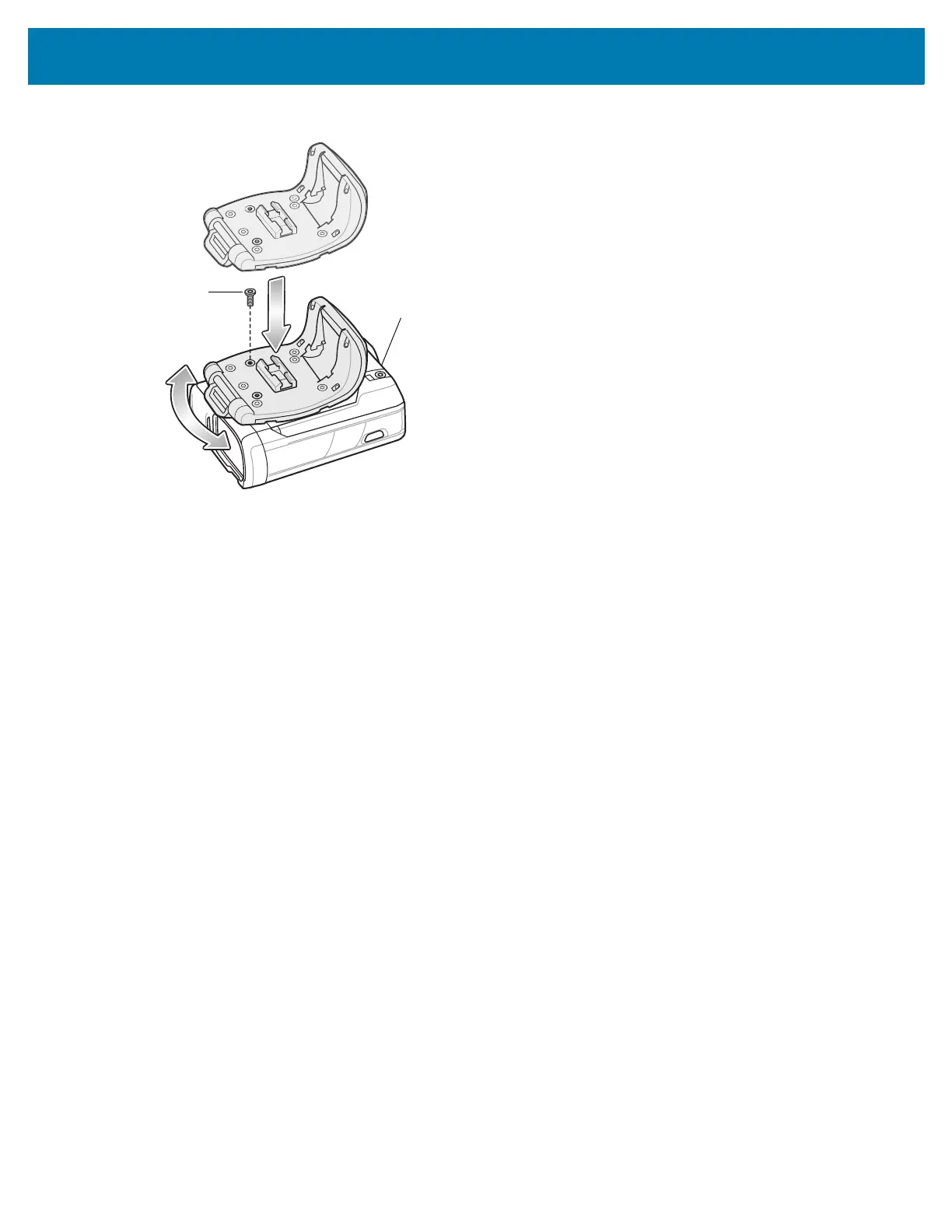
Figure 62 Installation of Trigger Assembly
4. Replace locking screw using aT6 Torx screwdriver. Torque screw to 2 kgf-cm.
5. Rotate the Trigger Assembly 1/4 turn counterclockwise.
6. Press the Large Comfort Pad onto the RS6000. When properly installed, the comfort pad locks into place.
7. Replace the comfort pad screw with a T6 Torx screwdriver to secure the comfort pad to the Trigger Assembly.
Torque screw to 2 kgf-cm.