6166 DC Voltage Current Source Operation Manual
5.1.2 2-Wire and 4-Wire Connections
5-2
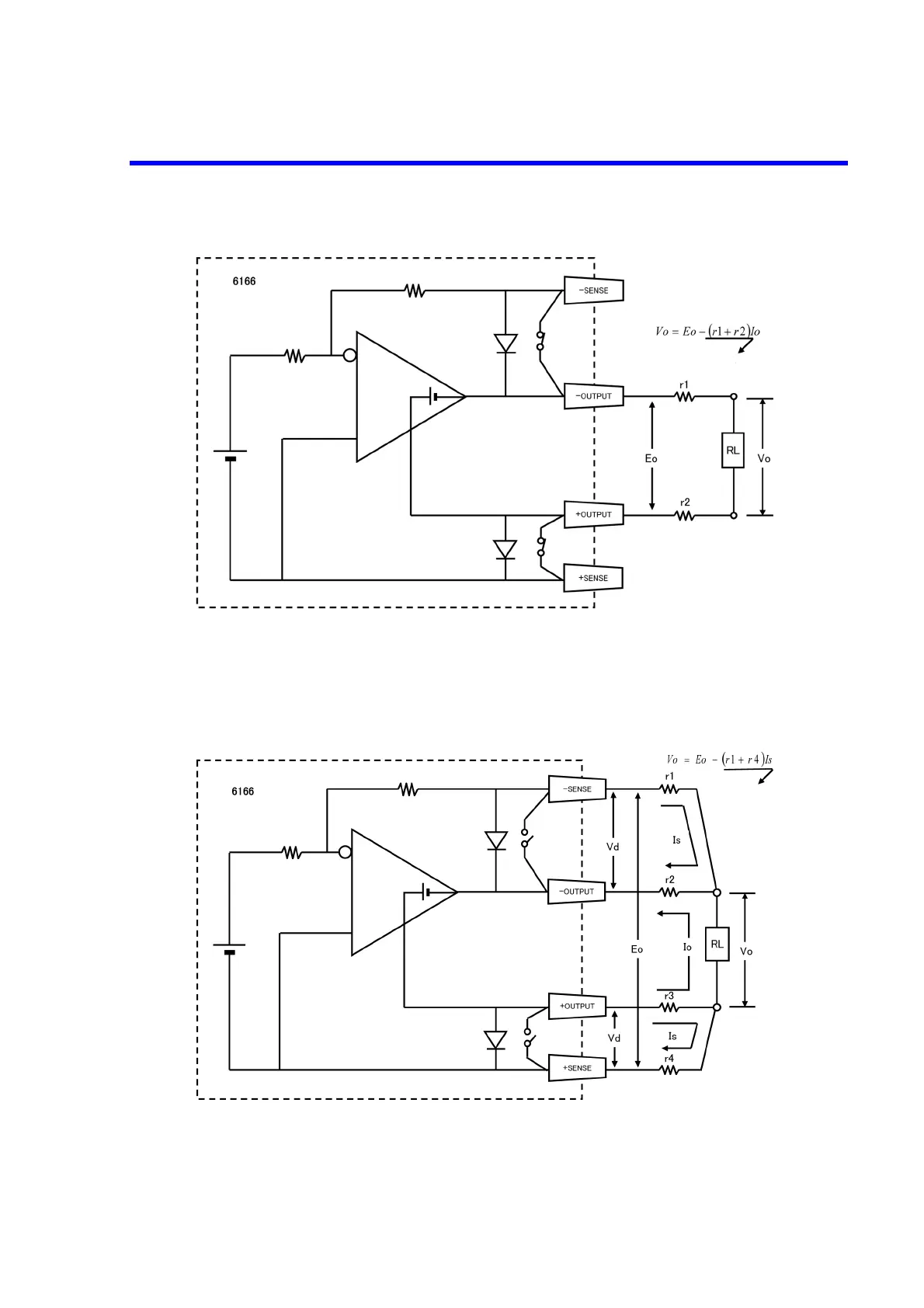
Figure 5-1 2-Wire Connection
Figure 5-2 4-Wire Connection
r1, r2: Lead resistance
Vo: Terminal voltage of RL
RL: Load
Error
r1, r2, r3, r4:Lead resistance
Vo: Terminal voltage of RL
RL: Load
Io: Load current
Error