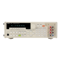
6166 DC Voltage Current Source Operation Manual
5. OPERATIONAL DESCRIPTIONS
5-1
5. OPERATIONAL DESCRIPTIONS
5.1 Connection with Load
5.1.1 Configuration of Output Terminals
The 6166 has four output terminals, two of which are positive terminals (red) and the other two are nega-
tive terminals (black). Both type of the terminals are divided into an OUTPUT terminal and a SENSE ter-
minal.
Normally, the OUTPUT terminals and the SENSE terminals are short-circuited (in 2-wire connection)
with the same polarity respectively. (The EXTERNAL SENSE key goes OFF.)
5.1.2 2-Wire and 4-Wire Connections
If there is considerable voltage drop due to cable resistance in the voltage ranges (1 V, 10 V, 100 V and
1000 V), connect the load in 4-wire connection. (The EXTERNAL SENSE key goes ON.)
The equivalent circuits used in 2-wire and 4-wire connections are shown on the next pages (Figure 5-1 and
Figure 5-2).
When the voltage is set to the full scale, the voltage sensing current (Is) is 40 A in the 1 V range or
100 A in the 10 V, 100 V and 1000 V ranges.
Thus, when the load current (Io) is less than the voltage sensing current (Is), using 2-wire connection offers
higher accuracy output.
For example, when connecting the load that has high impedance such as a digital multimeter, use 2-wire
connection.
On the contrary, when the load current (Io) is more than the voltage sensing current (Is), connect the load
in 4-wire connection (connect the OUTPUT and SENSE terminals at the load). This connection generates
an error due to the resistance of the cables connected to the SENSE terminals.
Table 5-1 shows the resistance of the cables connected to the SENSE terminals and the resulting error.
Table 5-2 shows the cable resistance per meter for reference.

 Loading...