6166 DC Voltage Current Source Operation Manual
5.5.4 TRIGGER IN Signal
5-16
5.5.4 TRIGGER IN Signal
The TRIGGER IN signal triggers the 6166 from the external device.
The following table shows the modes and their operations.
TRIGGER IN signal specification: TTL negative pulse
High: +2.4 V to +5.25 V
Low: 0 V to +0.4 V
Used connector: BNC
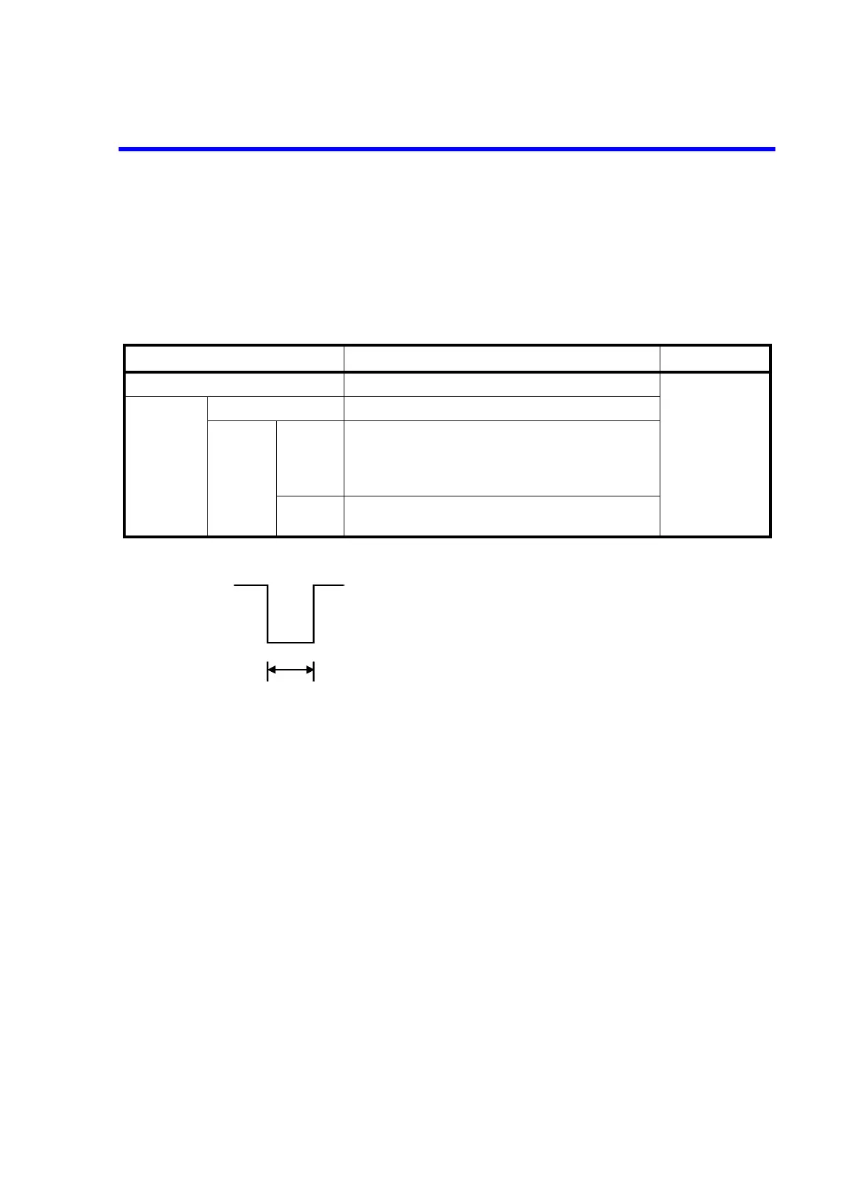
Table 5-5 TRIGGER IN Signal Operations
Program function ON/OFF Operation by TRIGGER IN signal Remarks
Program function OFF - No influence Refer to Section
3.8, "Program
Function."
Program
function ON
Memory recall - No influence
Memory
scan
Single
Repeat
- When scan operation is stopped, starts the operation
at the falling edge.
- During scan operation, pauses the operation at the
falling edge.
Hold - Sends forward the memory address by one step at
the falling edge.
+2.4 V to +5.25 V (or Open)
0 V to +0.4 V (or short-circuited to GND)
10 s or more