6166 DC Voltage Current Source Operation Manual
2.3 Rear Panel
2-13
2.3 Rear Panel
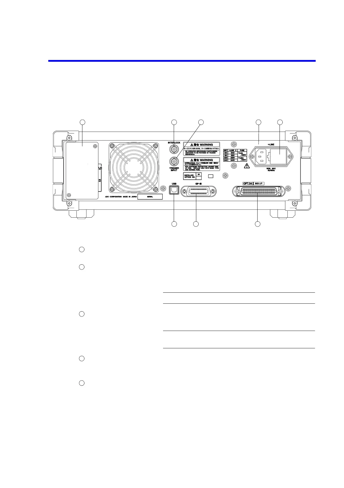
This section describes the connectors on the rear panel.
Figure 2-15 Rear Panel
AC power connector Used to connect the 6166 to the AC power supply by using the
supplied power cable.
Voltage selector and fuse holder
Voltage can be switched manually to match the AC power supply.
A fuse is contained inside.
CAUTION: Use an appropriate fuse.
INTERLOCK The interlock signal is input. The input resistance is approximate-
ly 10 k.
NOTE: The INTERLOCK function is disabled in BCD remote
status.
TRIGGER IN Used to start or pause scan operation by an external signal.
The input signal is a TTL negative pulse (Pulse width: 10 s or
over).
Rear output terminals The rear output terminals are covered with the terminal cover at
shipment.
When using the rear output terminals, remove the terminal cover
fixing screws.