6166 DC Voltage Current Source Operation Manual
9. SPECIFICATIONS
9-8
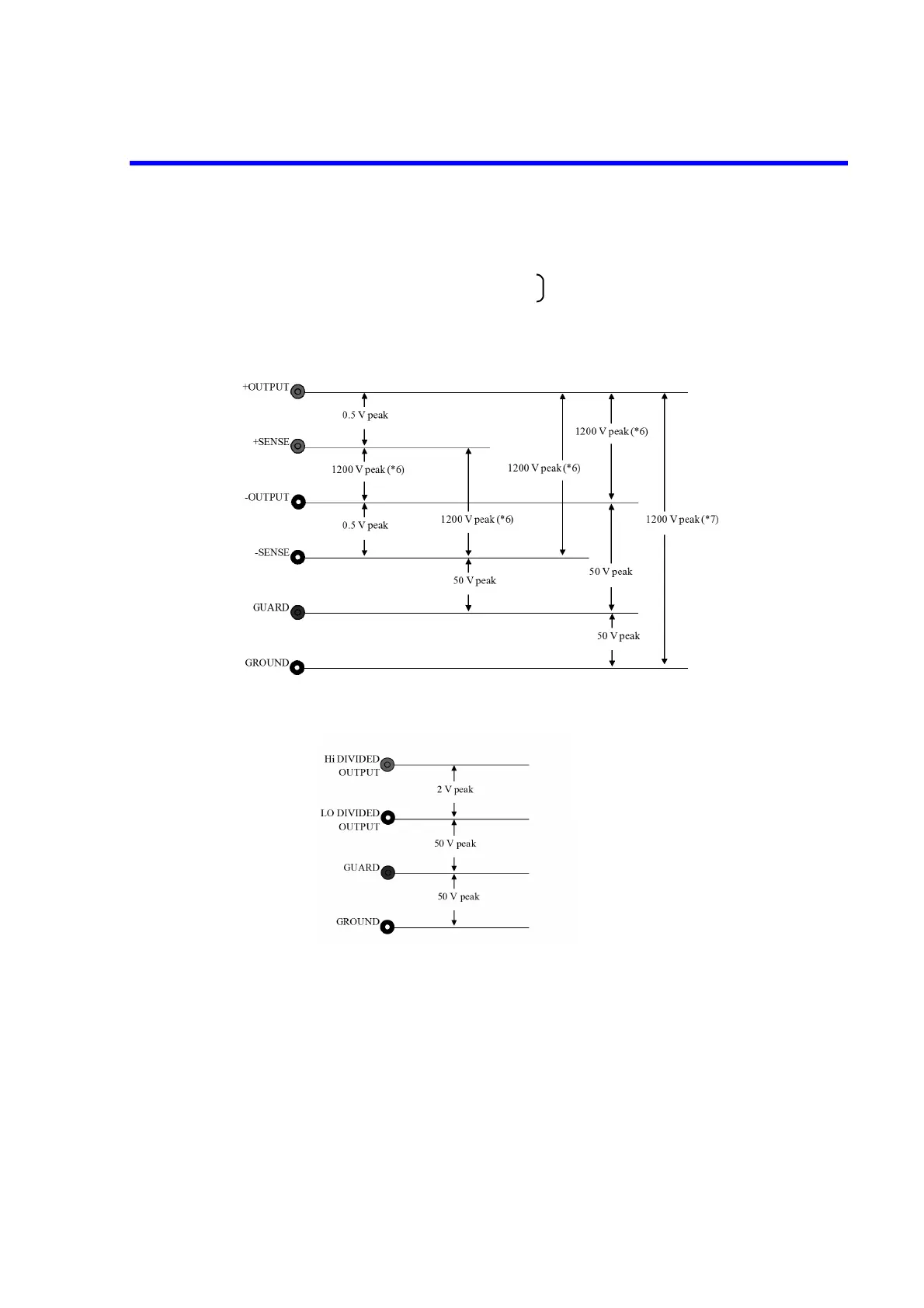
GUARD and chassis 50 V peak max
(*7) When the -OUTPUT terminal, the GROUND terminal and the GUARD
terminal are short-circuited
Figure 9-1 Maximum Input between Terminals
Figure 9-2 Maximum Input between Divider Output Terminals
Maximum remote sensing voltage between:
+OUTPUT and +SENSE 0.1 V peak max
-OUTPUT and -SENSE 0.1 V peak max
* The voltage between OUTPUT and SENSE must be 0.1 V or less includ-
ing voltage drop due to cable resistance. (Approx. 10 ppm error at 0.1 V)
GPIB interface: Compliant with IEEE-488.2-1987
Interface function SH1, AH1, T6, L3, SR1, RL1, PP0, DC1, DT1, C0, E2
Connector Amphenol 24 pin
USB interface: USB 2.0 Full-speed
Connector Type B
-OUTPUT
+SENSE
and GUARD 1200 V peak max (*7)