6166 DC Voltage Current Source Operation Manual
2.1.12 POWER Switch
2-10
5. GUARD terminal Guard terminal
The voltages printed between the terminals are described in the table below:
CAUTION: The front output terminals are connected to the rear output terminals respectively in parallel.
When the front output terminals are used, voltage or current is output from the rear output ter-
minals too.
*1 When applying voltage from the outside, refer to Section 5.2, "Source and Sink Operations."
*2 The voltage input from the outside is 2 V peak.
*3 When the -OUTPUT terminal, the GROUND terminal and the GUARD terminal are short-circuited
For more information on the maximum input between terminals, refer to Chapter 9, "SPECIFICA-
TIONS," Source Function.
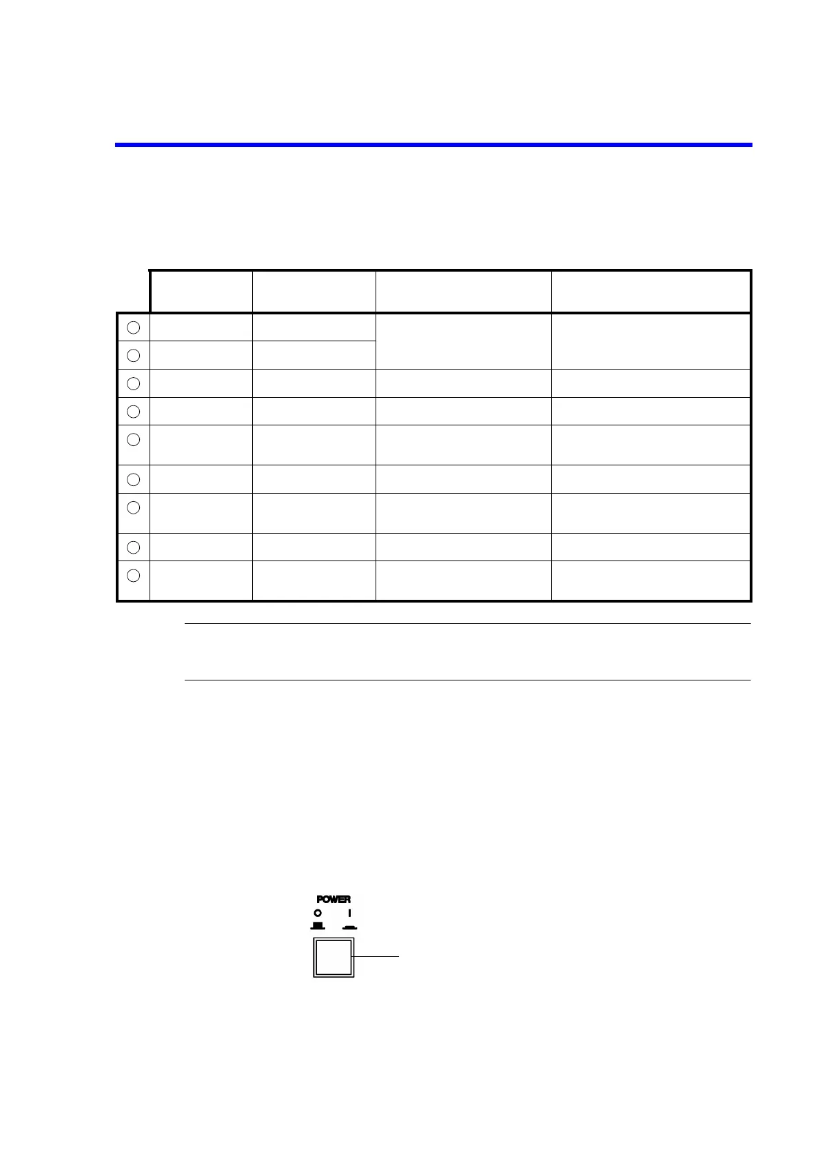
2.1.12 POWER Switch
Figure 2-13 POWER Switch
1. POWER switch Turns the power ON or OFF.
Table 2-1 Output Terminal Printing
Terminal 1 Terminal 2 Printing
Description between Terminal 1
and Terminal 2
+OUTPUT -OUTPUT MAX OUTPUT 1200 V
Maximum output 1200 V
*1
+SENSE -SENSE
+OUTPUT +SENSE 0.5 V PK MAX Maximum input 0.5 V peak
-OUTPUT -SENSE 0.5 V PK MAX Maximum input 0.5 V peak
HI DEVIDED
OUTPUT
LO DEVIDED
OUTPUT
MAX OUTPUT1.2 V
Maximum output 1.2 V
*2
-SENSE GROUND 50 V PK MAX Maximum input 50 V peak
LO DEVIDED
OUTPUT
GUARD 50 V PK MAX Maximum input 50 V peak
GROUND GUARD 50 V PK MAX Maximum input 50 V peak
GROUND +OUTPUT
+SENSE
1200 V PK MAX
Maximum input 1200 V peak
*3