6166 DC Voltage Current Source Operation Manual
5.5.5 INTERLOCK Input Signal
5-18
5.5.5 INTERLOCK Input Signal
The INTERLOCK signal is used to prevent unexpected outputs by connecting to the external device such
as fixture.
The INTERLOCK signal can be set to ON or OFF from the menu. For more information, refer to Section
3.9, "Menu Operation."
While this signal is enabled, the output status cannot be set to Operate when the input signal is at HI or
Open, and is set to Standby when the signal level changes from LO to HI in Operate status.
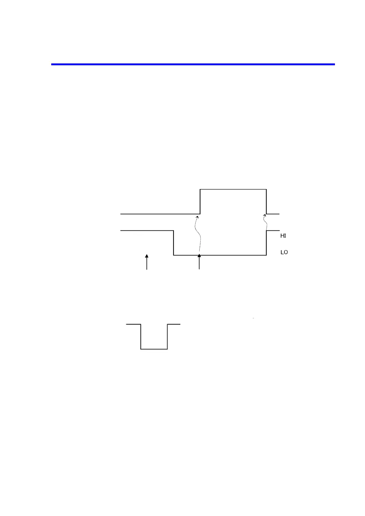
The following figure shows the INTERLOCK signal and its output status.
Figure 5-9 INTERLOCK Signal and Its Output Status
• INTERLOCK signal specification:
High: +2.4 V to +5.25 V
Low: 0 V to +0.4 V
Used connector: BNC
Output status
INTERLOCK signal
Turning Operate ON
Standby
Operate
TTL negative level
+2.4 V to +5.25 V (or Open)
0 V to +0.4 V (or short-circuited to GND)