Chapter 3 Installing the MV-5 and MV-10 Controllers
54 Adept MV Controller User’s Guide, Rev. B
In the industrial environment, nonperiodic overvoltage peaks may appear on
main power supply lines as a result of power interruptions to high-energy
equipment (such as a blown fuse on one branch in a 3-phase system). This will
cause high current pulses at relatively low voltage levels. The user shall take the
necessary steps to prevent damage to the controller system (such as by
interposing a transformer). See IEC 1131-4 for additional information.
Power Entry Module
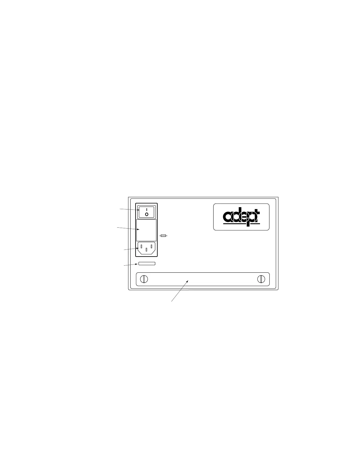
The power entry module located on the front of the controller is shown in Figure
3-1. It contains:
• the On/Off power switch ( I = On,
o
= Off)
• the fuse holder containing the two incoming AC line fuses (spare fuses are
stored in the fuse holder, see Figure 3-2.)
• the AC power cord socket
Figure 3-1. MV-5/MV-10 Power Entry Module
The CIP System Power Switch
The system power switch on the CIP does not directly control AC power to the
controller. Rather, it is designed to switch a relay that controls AC power to the
controller and to any other equipment you may want to switch along with the
controller. See “System Power Switch” on page 90 for details.
®
WARNING:
FOR CONTINUED PROTECTION
AGAINST RISK OF FIRE,
REPLACE ONLY WITH SAME
TYPE AND RATING OF FUSE.
USE ONLY WITH
250V FUSES
~100-240V
50/60HZ
5AT
On/Off Switch
Fuse Holder
AC Power Cord
Socket
Serial Number
Fan Filter Cover
On/Off Switch
Fuse Holder
AC Power Cord
Socket
Serial Number
Fan Filter Cover
Artisan Technology Group - Quality Instrumentation ... Guaranteed | (888) 88-SOURCE | www.artisantg.com