Appendix G Adept Supplied DeviceNet Hardware
382 Adept MV Controller User’s Guide, Rev. B
Adept Supplied DeviceNet Hardware
Adept supplies the following DeviceNet hardware in the CIP:
Micro-style 12 mm thread DIN connector (female). See 94 % $( for Pin
assignments.
Installed on the Adept XL series of robots is a DeviceNet cable that you can
use to route signals from the base of the robot to the outer link. See '$(
for a drawing of the connectors.
Connecting DeviceNet Hardware to the Adept DeviceNet Scanner
To connect DeviceNet components to the Adept DeviceNet Scanner, connect a
dropline to the female Micro-style 12 mm thread DIN connector on the back of the
CIP. Then you must configure the DeviceNet Scanner correctly using the
*/7)8
program. See the DEVICENET instruction in the V
+
Language
Reference Guide for detailed information about the DeviceNet software setup in
V
+
.
Adept does not supply 24V on the CIP to power the
DeviceNet bus. A separate power supply is required to power the
components on the DeviceNet bus.
The DeviceNet specification requires that the CAN_H
and CAN_L signal lines tolerate voltages up to 18V. Since the
supply voltage exceeds 18V, improperly wiring the supply voltage
to these signal lines may cause permanent damage.
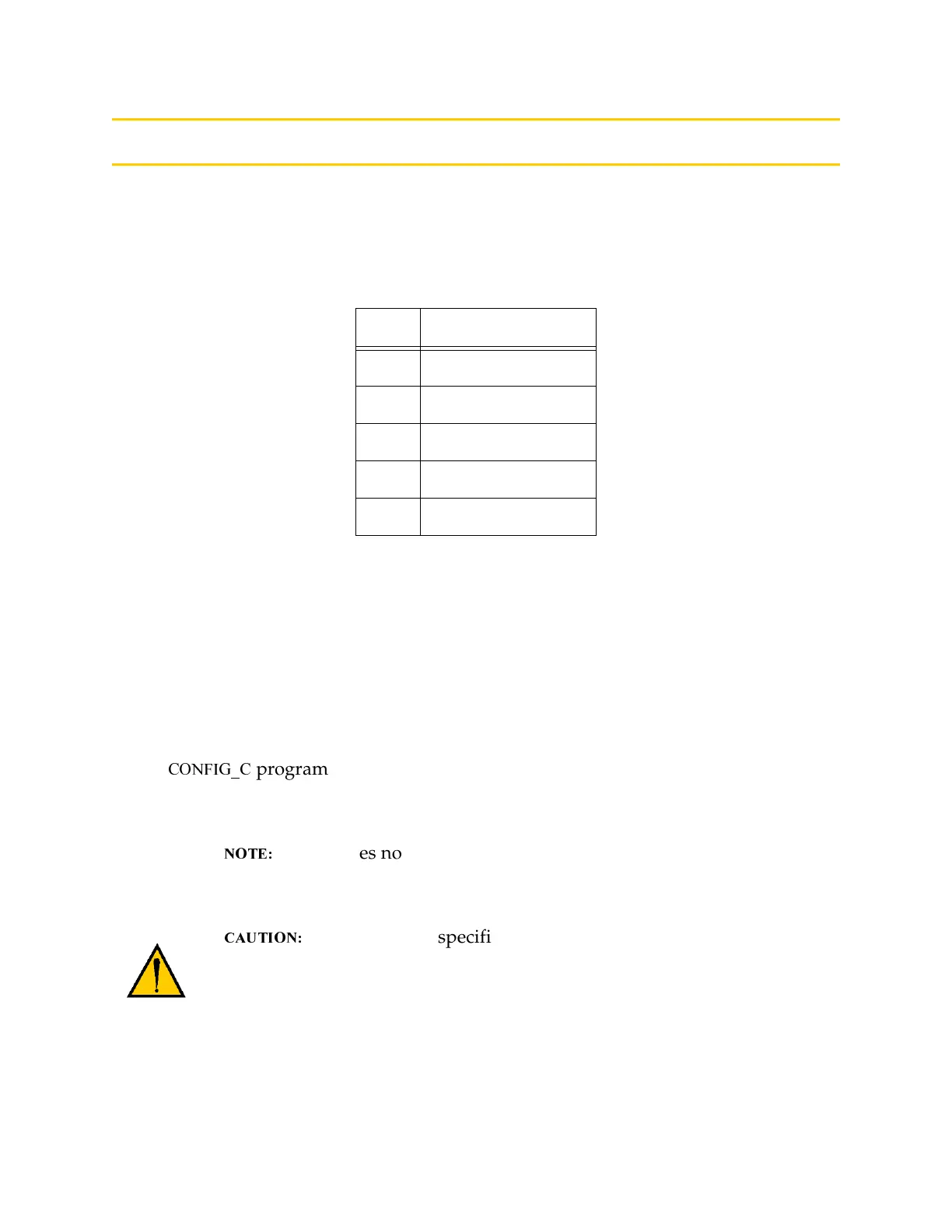
Table G-1. DeviceNet Signal to Pin Locations
Pin Signal Name
1Drain
2 V+
3V-
4CAN_H
5 CAN_L
Artisan Technology Group - Quality Instrumentation ... Guaranteed | (888) 88-SOURCE | www.artisantg.com