Chapter 4 AWC Board Connectors and Indicators
74 Adept MV Controller User’s Guide, Rev. B
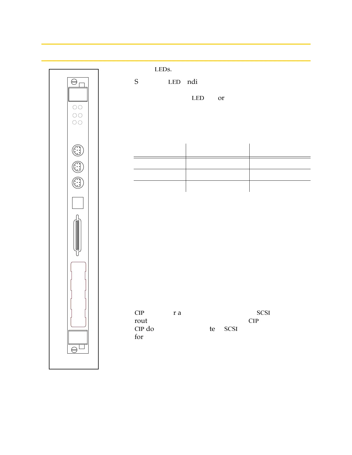
AWC Board Connectors and Indicators
➊
Status
0,6
s.
Six bicolor
0,6
s indicate diagnostic test, power control,
and communication status.
The left column of
0,6
s is for V
+
system status
information. See 5#,
.
The right column of LEDs gives the following status
information:
During system bootup the red SF/OK and ES/HPE LEDs
are lit and the red HD/LAN LED blinks. After system
bootup, the SF/OK LED should show green. If the
ES/HPE LED shows red, the E-Stop circuit is open.
During compact flash reads and writes, the HD/LAN
LED pulses red. When the AWC is active on an Ethernet
network, the HD/LAN LED pulses green.
➋
Two RS232 ports and one RS422/485 port. See ,
6%%#78* .
➌ Ethernet connector: Shielded RJ45 receptacle that
supports 10 BaseT communications. See
.
➍
%
connector accepts a standard 50-pin
''
cable that
routes signals and information to the
%
. Note that the
%
does not communicate in
''
format. See
for details.
LED Label Red LED Green LED
SF/OK System Fault System O.K.
ES/HPE ESTOP open High Power Enabled
HD/LAN Read/Write from CF Ethernet access
SF
OK
ES
HPE
HD
LAN
1
2
3
R
S
4
8
5
R
S
4
2
2
R
S
2
3
2
T
E
R
M
R
S
2
3
2
E
T
H
E
R
N
E
T
C
I
P
➊
➍
➌
➋
AWC
Artisan Technology Group - Quality Instrumentation ... Guaranteed | (888) 88-SOURCE | www.artisantg.com