Appendix G DeviceNet Physical Layer and Media
Adept MV Controller User’s Guide, Rev. B 387
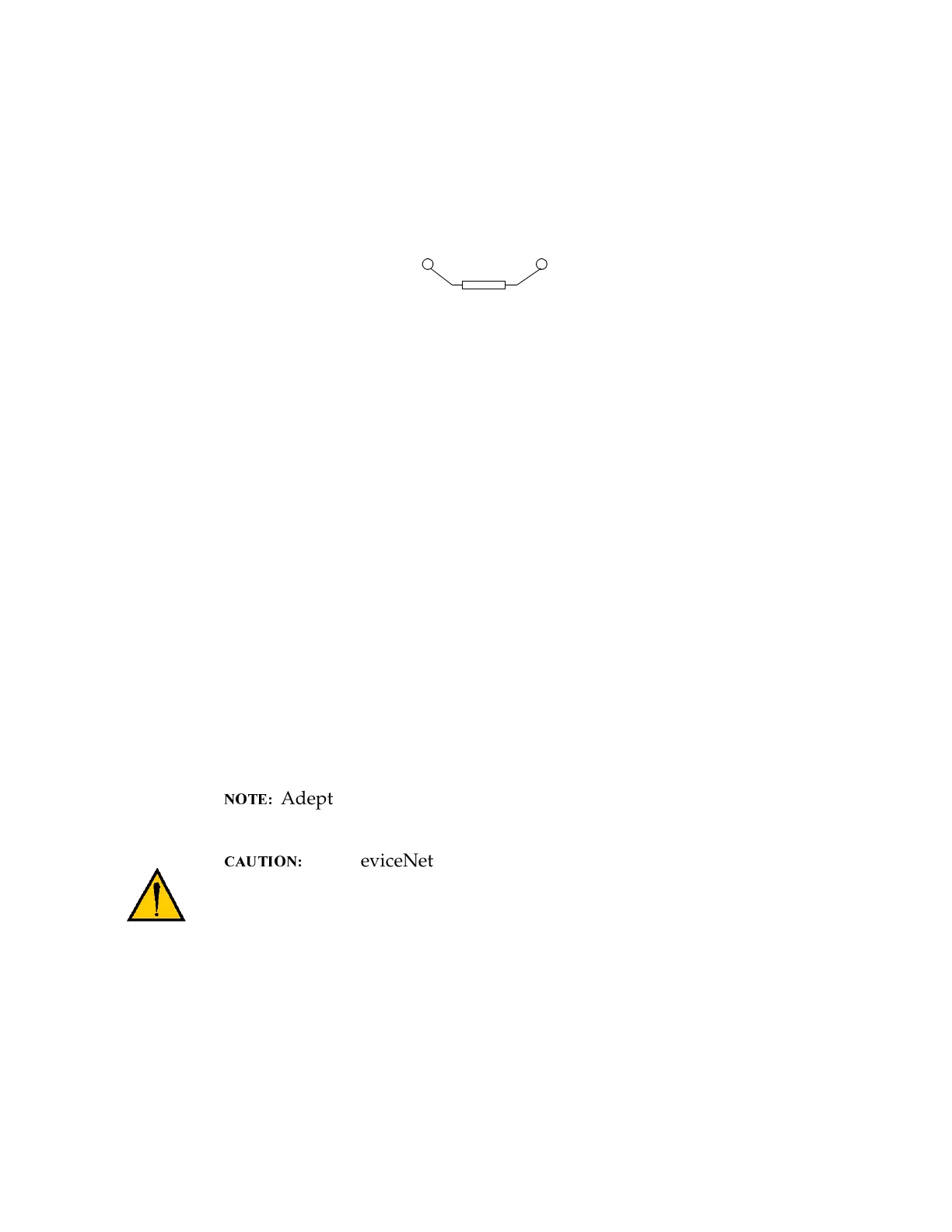
When using the open-style terminating resistor, connect a 121ohms, 1/4W resistor
to CAN_H and CAN_L (between blue and white data-pair wires).
Figure G-5. Example of a Terminating Resistor Installation on a DeviceNet Bus
Power Supply and the DeviceNet Bus
The DeviceNet network allows distribution of power supplies on the network
cable system. Follow these general rules to achieve a safe and reliable operation:
• Use power supplies rated at 24V
• Minimize installation problems by using one power supply with
sufficient current to operate all the attached nodes. This must comply
with the national and international safety standards.
• Make sure that each power supply incorporates current limit protection.
• Make sure each power supply is temperature compensated.
• Provide over current protection for each segment of your DeviceNet
cable installation.
Adept does not supply the 24V operating voltage for the
DeviceNet bus on the CIP or any other Adept component.
The DeviceNet specification requires that the CAN_H
and CAN_L signal lines tolerate voltages up to 18V. Since the
supply voltage exceeds 18V, improperly wiring the supply voltage
to these signal lines may cause permanent damage.
Power Capabilities of a DeviceNet Cable System
A DeviceNet cable system has several power rating constraints. The cable type
and the length of the cable specify the maximum current on a cable. Thick and
thin cable have:
Pin 4
CAN_H
Pin 5
CAN_L
Terminating Resistor
(121 ohms, 1/4W)
Artisan Technology Group - Quality Instrumentation ... Guaranteed | (888) 88-SOURCE | www.artisantg.com