Chapter 12 Additional DIO Boards
206 Adept MV Controller, User’s Guide, Rev. B
Labeling Sets of Cables
The optional Adept input and output cables for the DIO boards are the same for
each additional board that you add to a controller. Make sure to clearly label each
set of four cables so that they are identified with a specific DIO board. Also see the
warning on page 200 about swapping the two input cables or the two output
cables with each other.
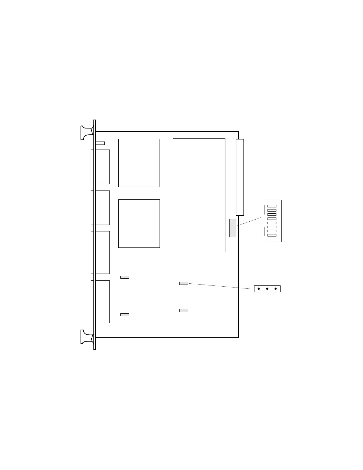
Figure 12-3. Switch and Jumper Locations on the DIO Board
Typical J3 to J6
B
A
1 2 3 4 5 6 7 8
OPEN
SW1
Adept DIO Board – Component Side
J3
J6
J4
J5
Adept DIO Board - Component Side
Typical J3 to J6
Artisan Technology Group - Quality Instrumentation ... Guaranteed | (888) 88-SOURCE | www.artisantg.com