Chapter 5 Connecting User-Supplied Digital I/O Equipment
Adept MV Controller User’s Guide, Rev. B 113
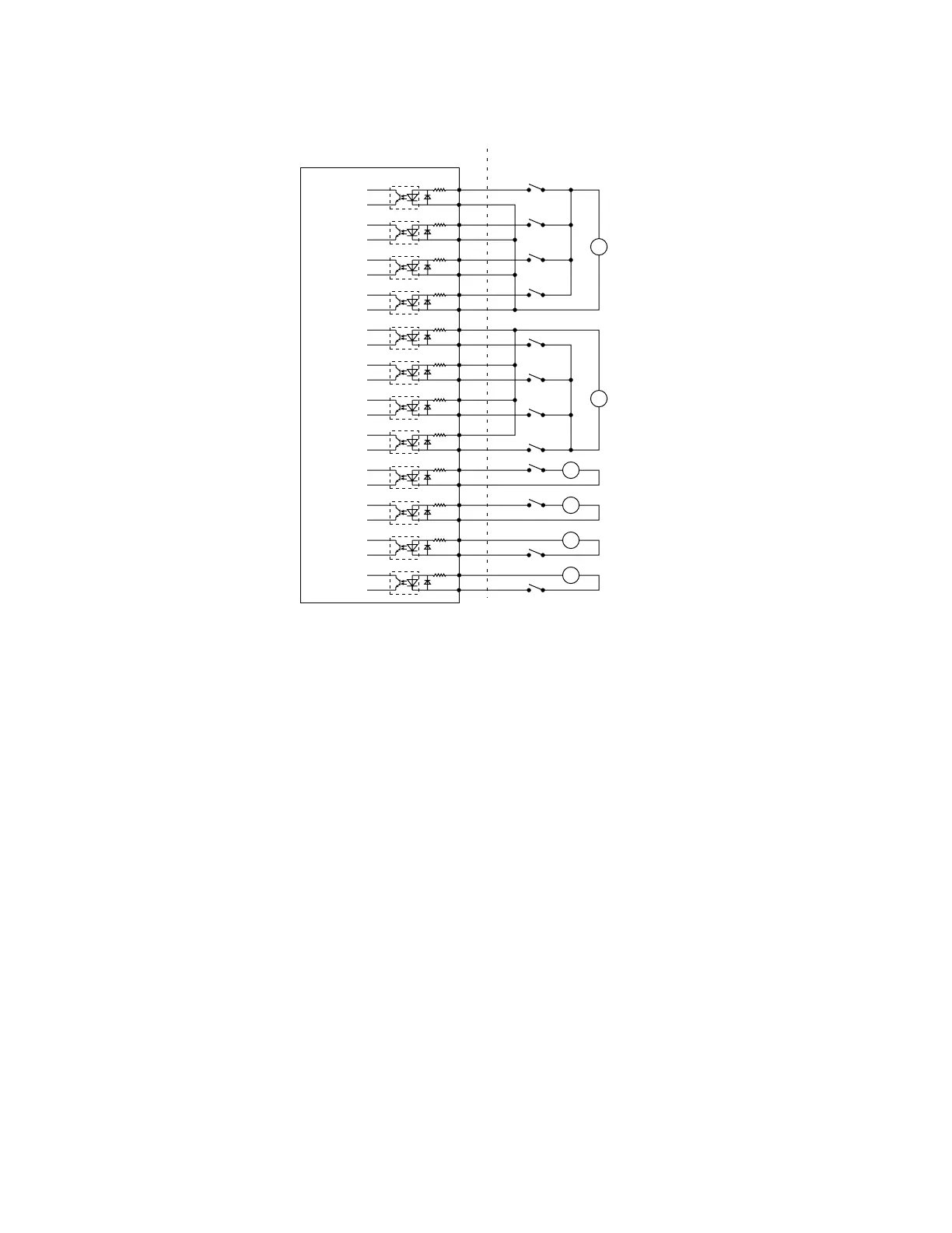
Figure 5-9. Digital Input Wiring Examples (JSIO Connector)
REACT Input Signals 1001 to 1012
Inputs 1001 to 1012 (only) may be used by the V
+
REACT and REACTI
instructions. See the V
+
Language Reference Guide for information on these
instructions. If you are going to use these instructions, you should plan your
digital I/O channel usage accordingly. (Inputs on the optional DIO board or CIP
JDIOx connectors cannot be used by the REACT and REACTI instructions.)
Fast Input Signals 1001 to 1004
In addition to functioning as normal input signals, signals 1001 to 1004 can have
the following special uses:
• Fast DIO V
+
Interrupt Events (INT.EVENT)
• Robot and Encoder Position Latch
• Vision Trigger
User power
supply
Example 1
Example 2
Example 3
User power
supply
Signal 1001
Signal 1002
Signal 1003
Signal 1004
Signal 1005
Signal 1006
Signal 1007
Signal 1008
Signal 1009
Signal 1010
Signal 1011
Signal 1012
+
–
+
–
+
–
+
–
+
–
+
–
Adept-Supplied Equipment User-Supplied Equipment
(Typical Examples)
(equivalent circuit)
1
2
3
4
5
6
7
8
9
10
11
12
13
14
15
16
17
18
19
20
21
22
23
24
+
–
+
–
+
–
+
–
+
–
+
–
+
–
+
–
+
–
+
–
+
–
+
–
Digital I/O Connector on CIP Module - Inputs
Sourcing
Sinking
Artisan Technology Group - Quality Instrumentation ... Guaranteed | (888) 88-SOURCE | www.artisantg.com