Chapter 9 Connections and Indicators
Adept MV Controller User’s Guide, Rev. B 175
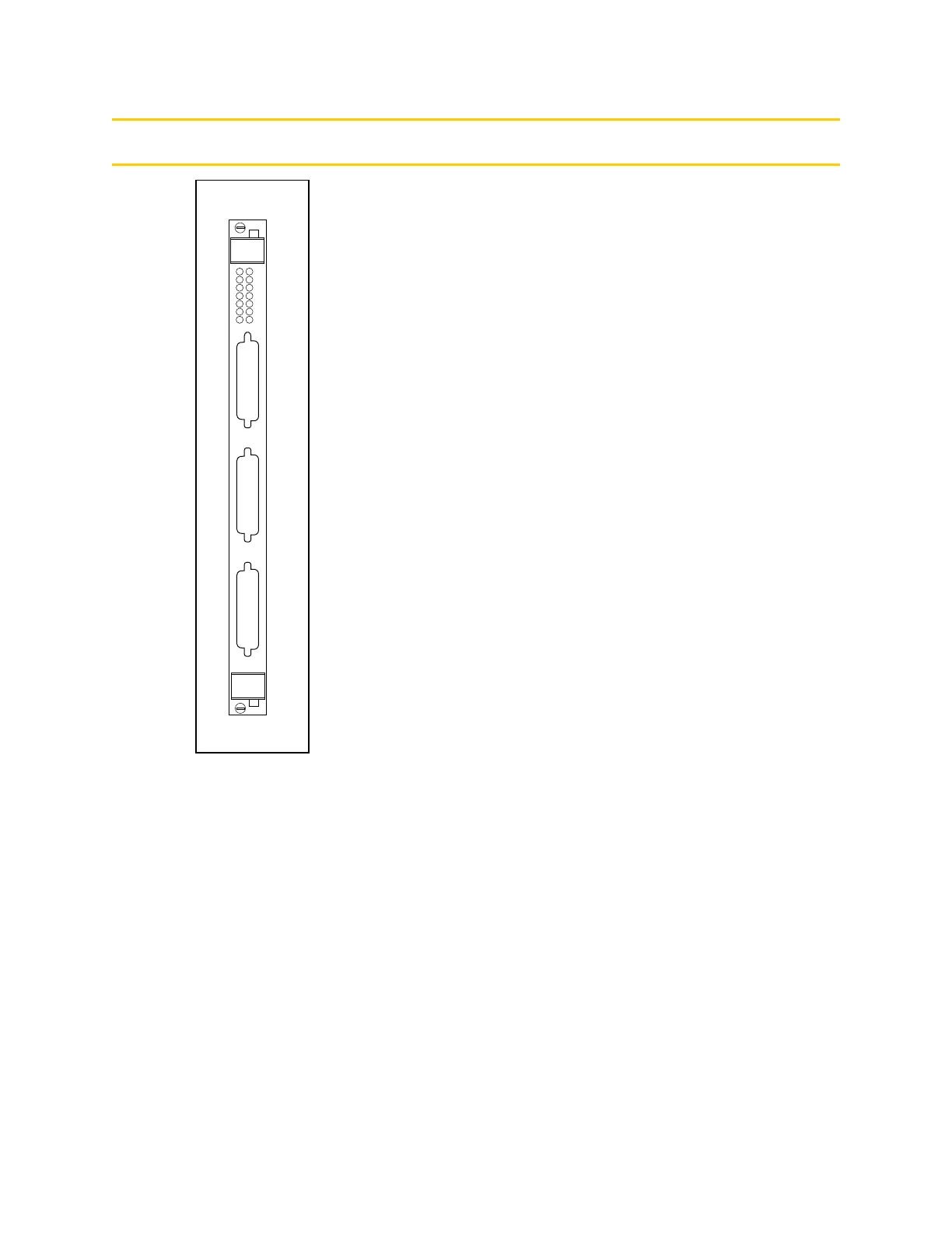
Connections and Indicators
➊
Red Status LEDs. When lit:
ES — indicates a latched E-Stop signal on the backplane
has been asserted from the MI6 board or somewhere else
in the system.
F1 — indicates a fault condition exists on Axis 1. The
cause could be an Overtravel or a Drive Fault. The same
applies to axes 2 through 6.
F2 — indicates a fault condition exists on axis 2.
F3 — indicates a fault condition exists on axis 3.
F4 — indicates a fault condition exists on axis 4.
F5 — indicates a fault condition exists on axis 5.
F6 — indicates a fault condition exists on axis 6.
➋ Yellow Status LEDs. When lit:
HPE — indicates the High Power Enable signal is
asserted.
DE1 — indicates the Drive Enable signal is asserted for
Axis 1.
DE2 — indicates the Drive Enable signal is asserted for
Axis 2.
DE3 — indicates the Drive Enable signal is asserted for
Axis 3.
DE4 — indicates the Drive Enable signal is asserted for
Axis 4.
DE5 — indicates the Drive Enable signal is asserted for
Axis 5.
DE6 — indicates the Drive Enable signal is asserted for
Axis 6.
➌ Encoder connector — a 44-pin D-Sub female connector
for the encoder cable to interface to encoder signals in the
installation.
➍ Machine connector — a 44-pin D-Sub female connector
for the machine cable to interface to the machine signals
in the installation.
➎ Servo connector — a 44-pin D-Sub female connector for
the servo cable to interface to the servo signals in the
installation.
E
N
C
O
D
E
R
M
A
C
H
I
N
E
HPE
DE1
DE2
DE3
DE4
ES
F1
F2
F3
F4
DE5
DE6
F5
F6
S
E
R
V
O
MI6
➊
➋
➌
➍
➎
Artisan Technology Group - Quality Instrumentation ... Guaranteed | (888) 88-SOURCE | www.artisantg.com