Chapter 6 Connections and Indicators
Adept MV Controller User’s Guide, Rev. B 133
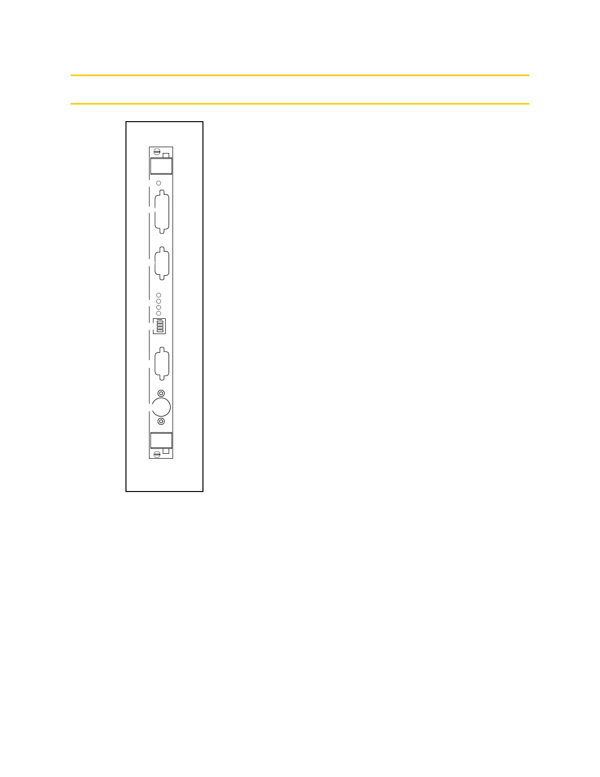
Connections and Indicators
➊
OK LED indicates that this board has passed its start-up
test.
➋
Video Bus connector — a 26-pin mini D-sub connector for
installing one end of the video bus connector in
AdeptVision systems. The other end of the connector
connects to the EVI board. (Not used in nonvision
systems.)
➌
Monitor connector — a 15-pin female mini D-sub
connector for the color monitor. See page 135.
➍
LEDs 1 to 4 are for Adept Service use only.
➎ DIP Switch (4 position) — see Table 6-1 for functions.
➏
Pointer connector — a 9-pin male D-sub connector for the
pointer cable from the Adept integrated
keyboard/trackball. Can also be used for a mouse or
touchscreen. See page 137 for details.
➐
Keyboard connector — a 5-pin female DIN connector for
the keyboard cable from the Adept integrated
keyboard/trackball. See page 136 for details.
NOTE:
On a graphics-based system, the V
+
system
monitor window is normally displayed on the
monitor connected to the VGB board. However, you
can redirect the system monitor input/output to the
RS-232/Term port on the processor board.
P
O
I
N
T
E
R
1
2
3
4
ON
2
3
41
V
I
D
E
O
B
U
S
M
O
N
I
T
O
R
KEYBOARD
OK
VGB
➊
➋
➌
➍
➎
➏
➐
Artisan Technology Group - Quality Instrumentation ... Guaranteed | (888) 88-SOURCE | www.artisantg.com