Chapter 7 VME Bus Address and Configuration
144 Adept MV Controller User’s Guide, Rev. B
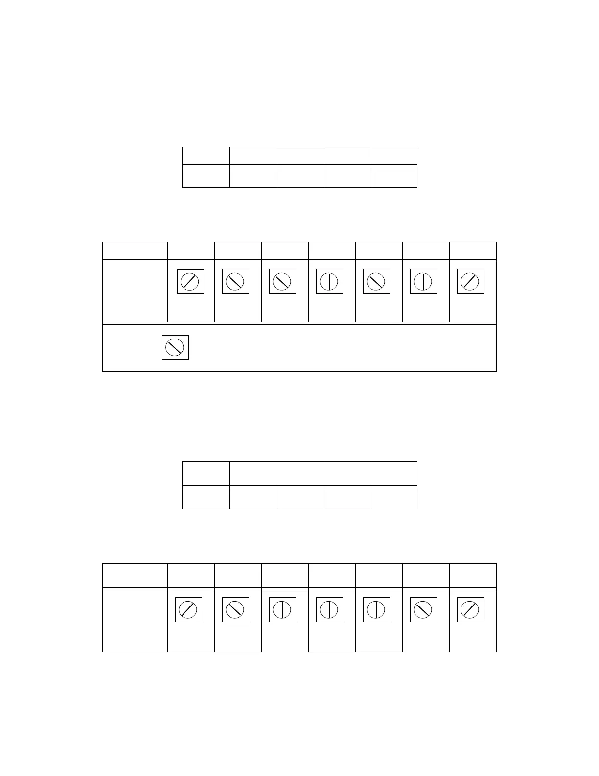
Settings for Normal RS-170 Cameras
The tables below show the settings for the acquisition switches when using a
normal RS-170 camera.
Settings for Pulnix TM-1001 Cameras
The tables below show the settings for the acquisition switches when using a
Pulnix TM-1001 camera.
Table 7-3. Acquisition Switch Settings for SW1
1234
SW1BBBB
Table 7-4. Acquisition Switch Settings for SW2 - SW8
SW2 SW3 SW4 SW5 SW6 SW7 SW8
Rotary
Switch
Slot
Position
Note:
Set SW5 to
for pixel clock output.
Table 7-5. Acquisition Switch Settings for SW1
1234
SW1 A B A A
Table 7-6. Acquisition Switch Settings for SW2 - SW8
SW2 SW3 SW4 SW5 SW6 SW7 SW8
Rotary
Switch
Slot
Position
A
B C
A B
C
A B
C
A
B
C
A
B
C
A
B C
A
A
B C
A B
C
A
B
C A
B
C
A B
C
A
B C
Artisan Technology Group - Quality Instrumentation ... Guaranteed | (888) 88-SOURCE | www.artisantg.com