Chapter 5 Introduction
Adept MV Controller User’s Guide, Rev. B 91
NET Switch
This switch should be left in the ”O” position.
Side Connectors
See '( for the location of the following connectors:
AWC Interface (JAWC)
Connects the CIP to the AWC board. The JAWC connector accepts a standard
50-pin SCSI cable. Note that the CIP does not communicate in SCSI format. See
#*,1 for details.
User Connector (JUSER)
All switch functions on the CIP can be duplicated external to the CIP using
signals from this connector. For example, an external ESTOP can be connected to
the User connector, and this will behave exactly like the ESTOP on the CIP.
Similarly, there is an output on the User connector that can be used to stop
external equipment when the CIP ESTOP is pressed. See <3.*%
- for details.
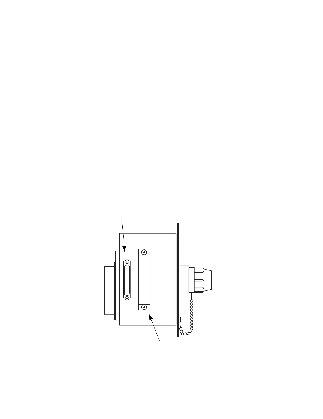
Figure 5-2. Controller Interface Panel (CIP) Side View
CIP SCSI Cable Connector
JUSER Connector
Artisan Technology Group - Quality Instrumentation ... Guaranteed | (888) 88-SOURCE | www.artisantg.com