Chapter 9 Jumper Settings and Resistor Configuration on MI3/MI6
Adept MV Controller User’s Guide, Rev. B 177
Jumper Settings and Resistor Configuration on MI3/MI6
See the AdeptMotion VME Developer’s Guide for information on the correct
settings for the switches, jumpers, and resistor packs on the MI3/MI6 board.
Connecting to User Equipment
The MI3/MI6 board connections to user equipment are divided into three groups:
the encoder, the machine, and the servo. Adept offers a set of cables and Motion
Interface mounting panels (MP6) that should be used to make connections
between the MI3/MI6 board and your equipment. Each connector on the
MI3/MI6 has a corresponding cable and MP6 mounting panel. The MP6 panels
can be installed on standard DIN mounting rails.
See the AdeptMotion VME Developer’s Guide for complete information on the
installation and setup of user equipment.
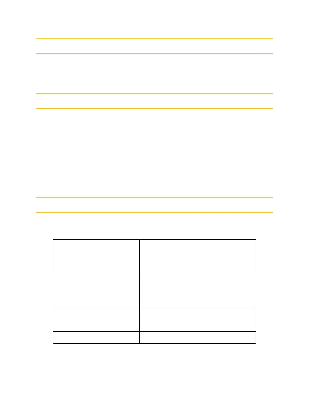
MI3/MI6 Board Specifications
Table 9-2. Technical Specifications
a
a
Specifications subject to change.
Electrical Power
Consumption
5 VDC at 4.0 A max
+12 V at 84 mA
–12 V at 21 mA
Maximum MI6 per controller MV-19: 4 MI-6
MV-5: 2 MI-6
MV-10: 4 MI-6
Number of axes of control 3 axes of control per MI-3 board
6 axes of control per MI-6 board
Width Occupies one backplane slot
Artisan Technology Group - Quality Instrumentation ... Guaranteed | (888) 88-SOURCE | www.artisantg.com