Chapter 4 AWC Module Serial I/O Ports
Adept MV Controller User’s Guide, Rev. B 85
LED Status Indicators on the AWC
The LEDs on the front of the AWC give the following information about the status
of the main AWC CPU.
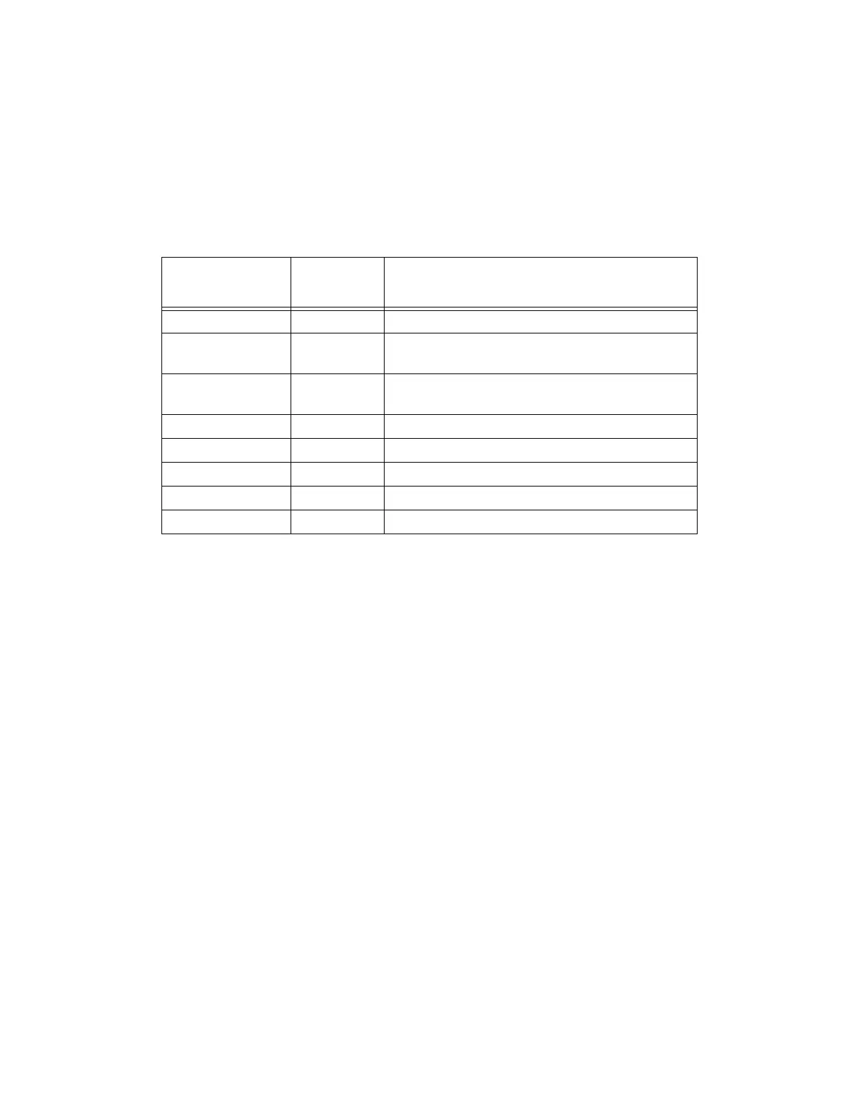
O = Off G = Green R = Red
If the AWC displays any of the above errors, contact Adept Customer Service.
Table 4-10. LED Status Indicators
LED Display
1 2 3 Error # Description
O-O-O 0 No error.
O-O-R 1
System clock is dead or too fast. Clock interrupts
are not being received.
O-R-O 2
Hardware configuration error. Address
switches/SYSCTL wrong.
O-R-R 3 Graphics board failure. VGB not responding.
R-O-O 4 Memory test failure. Free storage error.
R-R-O 6 Software serial I/O configuration error.
G-O-O C Uninitialized trap.
G-O-G D Bus error detected.
Artisan Technology Group - Quality Instrumentation ... Guaranteed | (888) 88-SOURCE | www.artisantg.com