Chapter 7 VME Bus Address and Configuration
Adept MV Controller User’s Guide, Rev. B 143
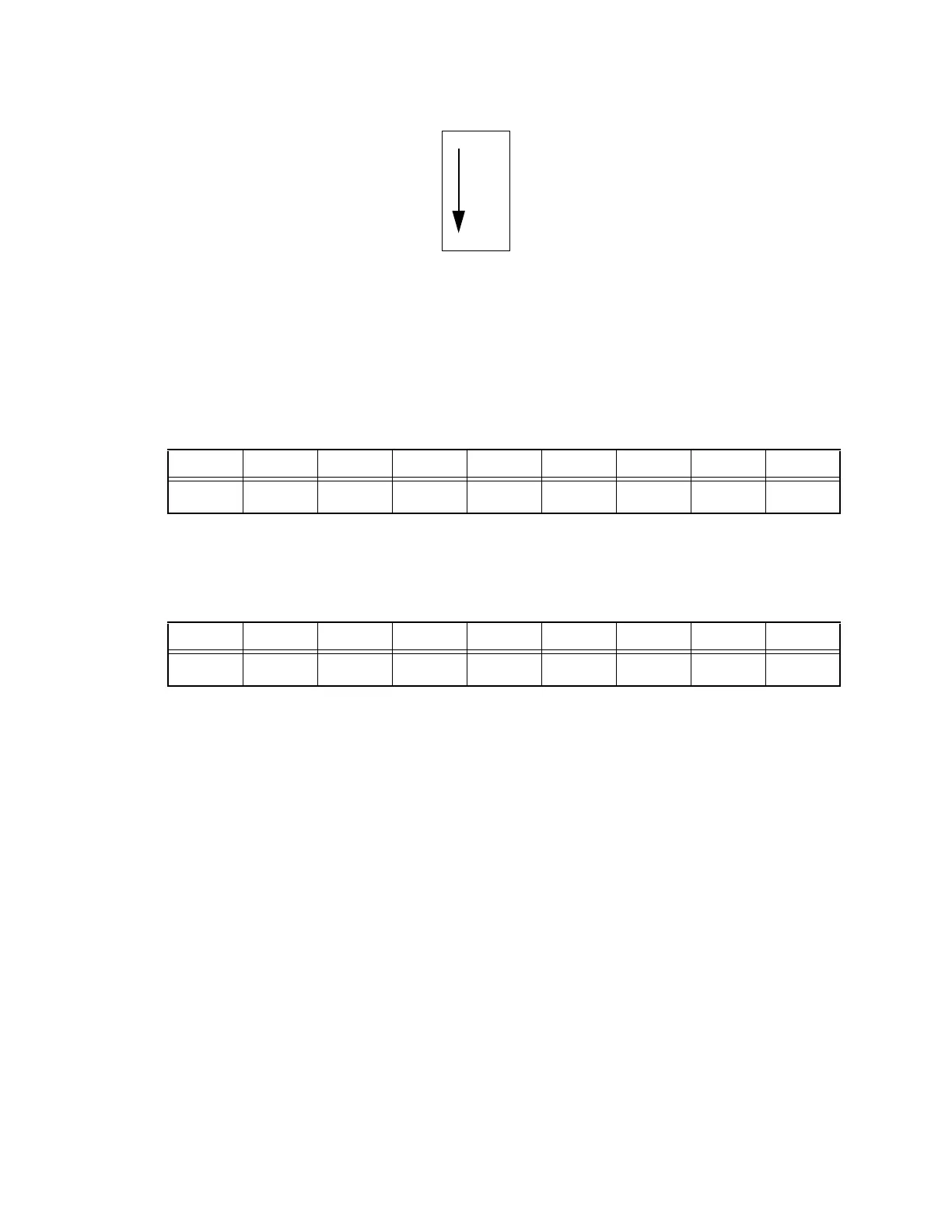
Figure 7-2. Rocker (Dip) Switch Positions for SW1 on Motherboard
and Daughterboard
Refer to the settings shown in Table 7-1 when installing the first EVI board into
your Adept MV controller.
If you add a second EVI board in your controller, refer to the settings shown in
Table 7-2 when installing the second board.
SW1-3 (3rd switch on SW1) selects either:
• B: POS_LATCH 1 and VIS_TRIGGER 1 (recommended for EVI board 1)
or...
• A: POS_LATCH 2 and VIS_TRIGGER 2 (recommended for EVI board 2)
All other switches on SW1 should be set as shown above.
Acquisition Switch Setting Mode
The acquisition mode switches are located on the EVI daughterboard. There is
one DIP switch bank (SW1) and seven three-position rotary switches (SW2 - SW8)
that must be set. See Figure 7-1 for the location of the acquisition mode switches
on the EVI board.
Table 7-1. Switch Settings for EVI Board 1
12345678
SW1B B AAAAAA
Table 7-2. Switch Settings for EVI Board 2
12345678
SW1B B AAAAB A
A
B
Artisan Technology Group - Quality Instrumentation ... Guaranteed | (888) 88-SOURCE | www.artisantg.com