Chapter 7 Installing Camera Cables
152 Adept MV Controller User’s Guide, Rev. B
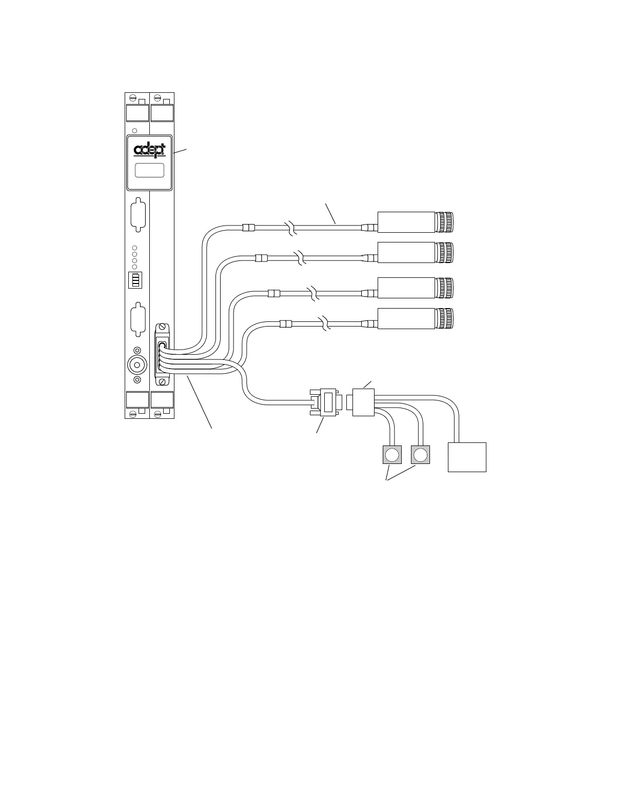
Figure 7-7. Camera Cable Installation Drawing (RS-170)
Connecting the Cables to the Pulnix TM-1001 Camera
This section describes the steps for connecting the cables between the EVI board
and the Pulnix TM-1001 cameras (see Table 7-8). For Pulnix TM-1001 camera
switch settings, refer to Appendix I of the AdeptVision User’s Guide.
1. Turn off the Adept MV controller.
C
A
M
E
R
A
S
/
S
T
R
O
B
E
S
EVI
P
O
I
N
T
E
R
1
2
3
4
ON
2
3
41
M
O
N
I
T
O
R
KEYBOARD
OK
VGB
Strobe/Power
Connector
User 12VDC
Power Supply
to Drive
Cameras
User-Supplied
9-pin Male D-Sub
Connector
Up to Two
Optional
Strobe
Lamps
Video Bus Coupling
Installed
Up to four cameras
can be installed.
Four-Camera
Breakout Cable
10-Meter Camera
Cable, one for
each camera
VIDEO
BUS
Video Bus Coupling
Installed
10-Meter Camera
Cable, one for each
camera
Up to four cameras
can be installed
User-supplied 9-pin
Male D-sub
Connector
Four-Camera
Breakout Cable
Strobe/Power
Connector
Up to Two Optional
Strobe Lamps
User 12VDC
Power Supply to
Drive Cameras
Artisan Technology Group - Quality Instrumentation ... Guaranteed | (888) 88-SOURCE | www.artisantg.com