Chapter 5 Connecting Customer-Supplied Safety and Power Control Equipment to the CIP
Adept MV Controller User’s Guide, Rev. B 103
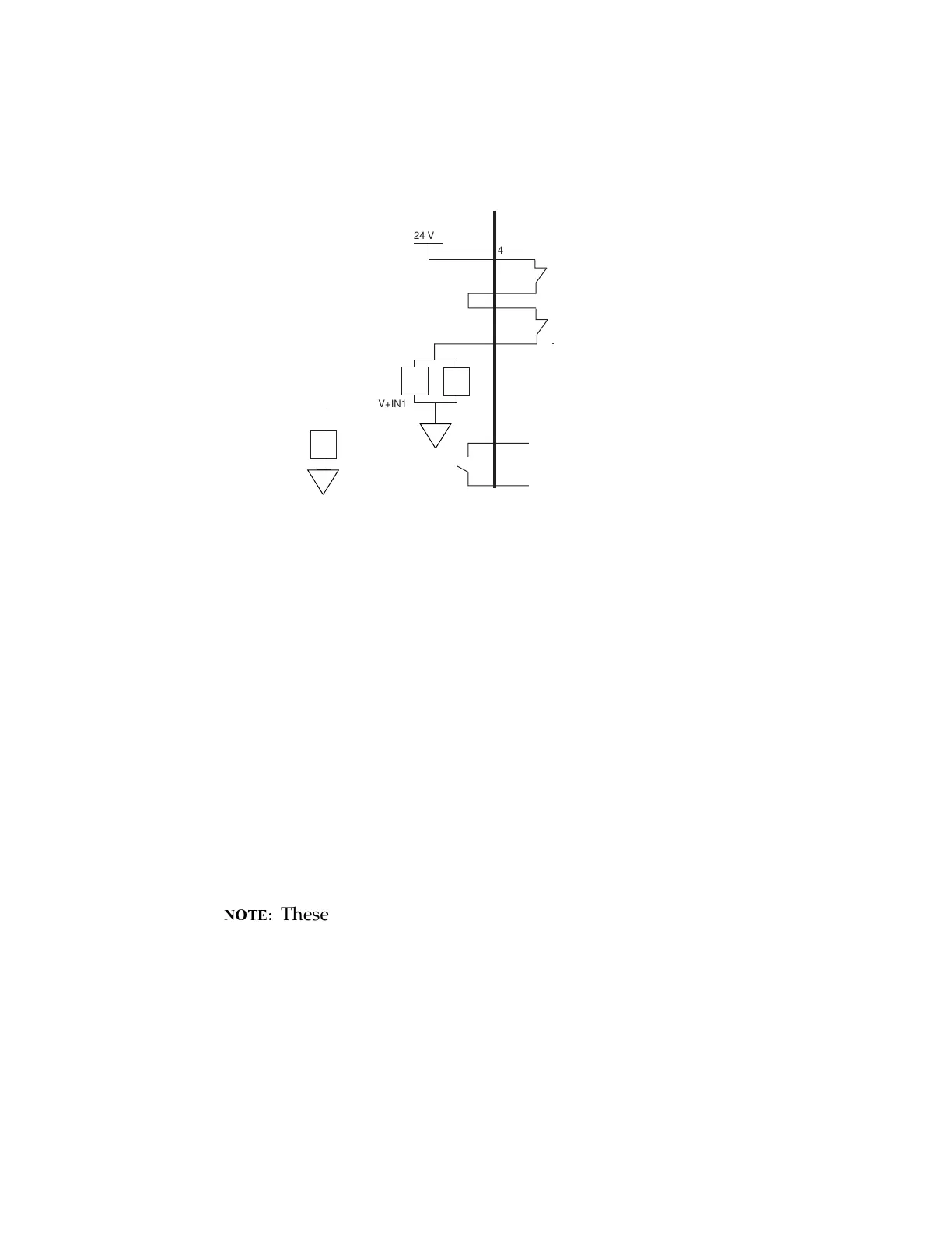
Figure 5-7. JSIO Emergency Stop Circuit
Emergency Stop Circuit
The CIP provides two methods for user-supplied Emergency Stop (E-stop)
circuits. This gives the AWC system the ability to duplicate E-stop functionality
from a remote location using voltage-free contacts. Both the JUSER connector and
the JSIO connector provide external E-stop connections into the CIP.
The JUSER connector has a two channel E-stop input on pins 4 to 23 and 5 to 24.
The JSIO connector provides a single channel E-stop which controls two relays in
the CIP. This E-stop is for compatibility with legacy applications using the 50 pin
connector on the SIO board. These JSIO pins are 41 to 43 and 42 to 44 (see '
(, '(, '(0, and 94%( for the customer E-stop circuitry). The
two required connections will be arranged in series.
These pins must be shorted if not used. Both channels must
open independently if used. Although an Emergency Stop will
occur, the CIP will malfunction if one channel is jumpered closed
and the other channel is opened. It will also malfunction if the
channels are shorted together.
JSIO 50-pin D-sub
FM
CIP Connections
User Supplied Connections
24 V
41
43
44
42
45
46
Auxiliary ESTOP
User ESTOP
V+ Passive
ESTOP Out
V+ High
Power On
- Legacy SYSIO
ESTOP Inputs
(Jumper closed when
not used)
V+IN1
PE 1
PE1
V+IN2
E
E
User-Supplied Connections
CIP connectors
Auxilliary ESTOPs
User ESTOP
-Legacy SYSIO
inputs (jumper
closed when not
used)
V
+
Passive
ESTOP out
V
+
High
Power on
Artisan Technology Group - Quality Instrumentation ... Guaranteed | (888) 88-SOURCE | www.artisantg.com