Chapter 7 VME Bus Address and Configuration
142 Adept MV Controller User’s Guide, Rev. B
VME Bus Address and Configuration
The EVI board will be configured as board 1 unless the system is running the dual
AdeptVision option, in which case the second EVI board will be board 2. If you
have only one EVI board installed, it will be set correctly when the controller is
shipped to you.
EVI Motherboard DIP Switch Setting
If you install a new EVI board (as a replacement part or upgrade) or have the dual
vision option, see the tables below for the address switch settings. The shaded
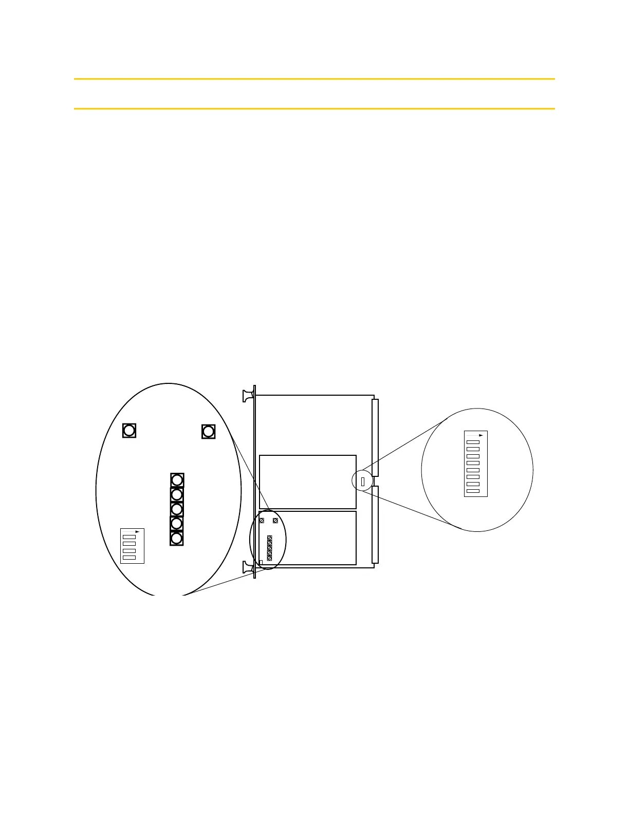
cells indicate the settings that are different for each board. See Figure 7-1 for the
location of SW1 on the EVI board. See Figure 7-2 for the position of the A and B
settings.
NOTE:
When setting the switches, you should rotate the board 90
degrees clockwise from the orientation shown in Figure 7-1 (the
VME bus connectors will be pointing toward you).
Figure 7-1. Switch Locations on EVI Board
Adept EVI Board – Component Side
1 2 3 4 5 6 7 8
4 3 2 1
SW1
SW2
SW3
SW4
SW5
SW6
SW7
EVI Mother Board
DIP Switches
EVI Daughter Board
DIP & Rotary
Switches
SW8
EVI Daughter Board
DIP and Rotary
Switches
Adept EVI Board - Component Side
EVI Mother Board
DIP Switches
Artisan Technology Group - Quality Instrumentation ... Guaranteed | (888) 88-SOURCE | www.artisantg.com