B-32 E6198B Switch/Load Unit User Manual
B Register Definitions
(>500 μs). The timers restart whenever the registers controlling
the respective relays are written to or the card is reset. The card
remains in the busy state until both timers have timed out.
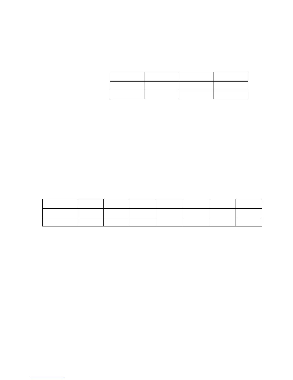
• Read Only
• Undefined bits read back as all 1s
• BUSY~: 0 = Busy, 1 = Ready
Current Sense Select (W) Base + 3
h
This register controls the current sense (Isense) relays of the
card and enables the differential amplifier. (See Figure B-10.)
Since only one current sense channel at a time per slot is
allowed, these channel selects are encoded. This allows
selection of zero or only one current sense relay at a time.
Writing to this register starts the reed relay timer.
• Write Only
• Undefined bits read back as all 1s
• DSS: Differential amplifier select. Set to 1 to place diff amp
into Isense path.
• CSS: current sense select (Isense). Bits 0-4 select the channel
to connect to the Isense bus.
• Valid CSS values are: 01-10
2h
. For example,
01
h
selects ch1
02
h
selects ch2
etc.
0F
h
selects ch15
10
h
selects ch16
Bit CC8 7-1 0
Purpose
CC8 Undefined BUSY~
Setting state all 1s state
Bit 76-543210
Purpose
DSS Undefined CSS4 CSS3 CSS2 CSS1 CSS0
Setting Select No. all 1s Select No. Select No. Select No. Select No. Select No.
 Loading...


