Protected by copyright. Copying for private or commercial purposes, in part or in whole, is not
permitted unless authorised by AUDI AG. AUDI AG does not guarantee or accept any liability
with respect to the correctness of information in this document. Copyright by AUDI AG.
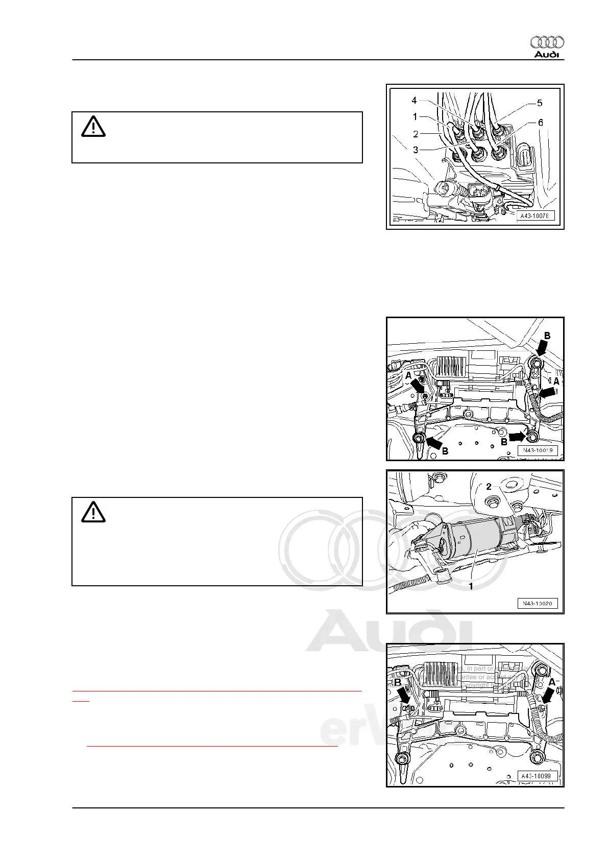
– Remove air line -2- and then air line -1- from solenoid valve
block.
Caution
Air lines -3- and -6- must not be disconnected.
1 - black, internal air line between solenoid valve block and
compressor
2 - Green, air line toward right front air spring shock absorber
3 - Red, air line toward left rear air spring shock absorber
4 - violet, air line to left front air spring damper
5 - Blue, air line toward pressure reservoirs
6 - Yellow, air line toward right rear air spring shock absorber
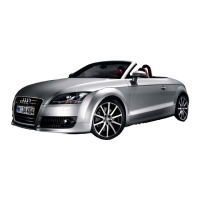
– Pull air lines out of bracket at underbody.
– Remove nuts -arrows A- for air supply unit.
– Remove bolts -arrows B- and secure air supply unit with brack‐
et (second mechanic required).
– Lower air supply unit with bracket enough at front to remove
air supply unit -1-.
Caution
♦ Make absolutely sure that the solenoid valve block -2- is
moved from underbody as little as possible.
♦ Furthermore, the air lines must not be kinked or stretched
under any circumstance
Installing
Install in reverse order of removal. Note the following:
– First tighten nut -arrow A- and then nut -arrow B- to avoid ten‐
sion in rubber bushing.
Tightening specifications, refer to
⇒ “4.4 Air Supply Unit and Solenoid Valve Block Overview”, page
225 .
– Install right underbody trim, refer to ⇒ Rep. Gr. 50
– Place vehicle on wheels, refer to
⇒ “4 Positioning Vehicle on Hoist and Wheels”, page 10 .
If the air supply unit was replaced, then the Level Control System
Compressor Relay - J403- must also be replaced. Component
location: Refer to Wiring Diagrams.
Audi Q7 2007 ➤
Suspension, Wheels, Steering - Edition 01.2014
4. Pneumatic Level Control System 229