Protected by copyright. Copying for private or commercial purposes, in part or in whole, is not
permitted unless authorised by AUDI AG. AUDI AG does not guarantee or accept any liability
with respect to the correctness of information in this document. Copyright by AUDI AG.
5.14 Rear Axle Camber, Adjusting
– Remove connector nut -1- and install new nut as far as stop.
– Adjust camber by rotating eccentric bolt.
Note
The maximum adjustment range is 90° to left or right of center
position.
– Tighten connector nut -1-, refer to -Item 17-
⇒ Item 17 (page 139) .
– After connector nut -1- has been tightened, check camber val‐
ue again.
5.15 Rear Axle Toe, Adjusting
– Remove connector nut -2- and install new nut as far as stop.
– Adjust toe by rotating eccentric bolt.
Note
♦
The maximum adjustment range is 90° to left or right of center
position.
♦
The geometric drive axle is automatically changed when indi‐
vidual toe settings are changed.
– Tighten nut -2-, refer to -Item 11- ⇒ Item 11 (page 139) .
– After nut -2- has been tightened, check toe value again.
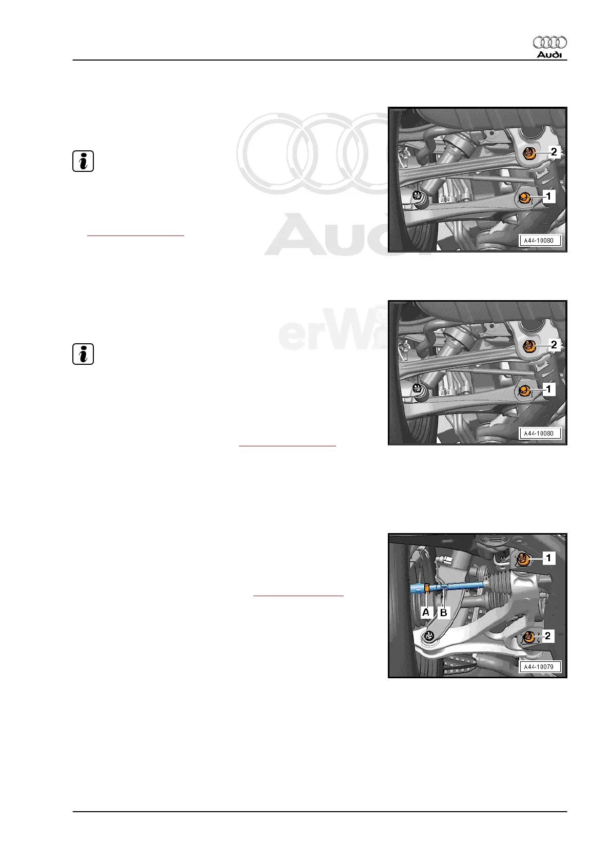
5.16 Front Axle Toe Angle, Checking and Ad‐
justing
– Loosen lock nut -A-.
– Adjust toe on left and right-hand wheels with hex -B-.
Be sure that boots are not twisted after turning tie rods!
Twisted boots wear out quickly.
– Tighten lock nut -A-, refer to -Item 2- ⇒ Item 2 (page 299) and
check toe-in again.
After tightening lock nut -A- it is possible that the value deviates
slightly.
If the measured toe nevertheless lies within the tolerance, the
adjustment is correct.
Audi Q7 2007 ➤
Suspension, Wheels, Steering - Edition 01.2014
5. Wheel Alignment 255