Protected by copyright. Copying for private or commercial purposes, in part or in whole, is not
permitted unless authorised by AUDI AG. AUDI AG does not guarantee or accept any liability
with respect to the correctness of information in this document. Copyright by AUDI AG.
Removing
Note
An axle alignment may be required. Refer to
⇒ “5 Wheel Alignment”, page 247 .
– With vehicles with air suspension, place vehicle on hoist, refer
to ⇒ “4 Positioning Vehicle on Hoist and Wheels”, page 10 .
– Remove wheel.
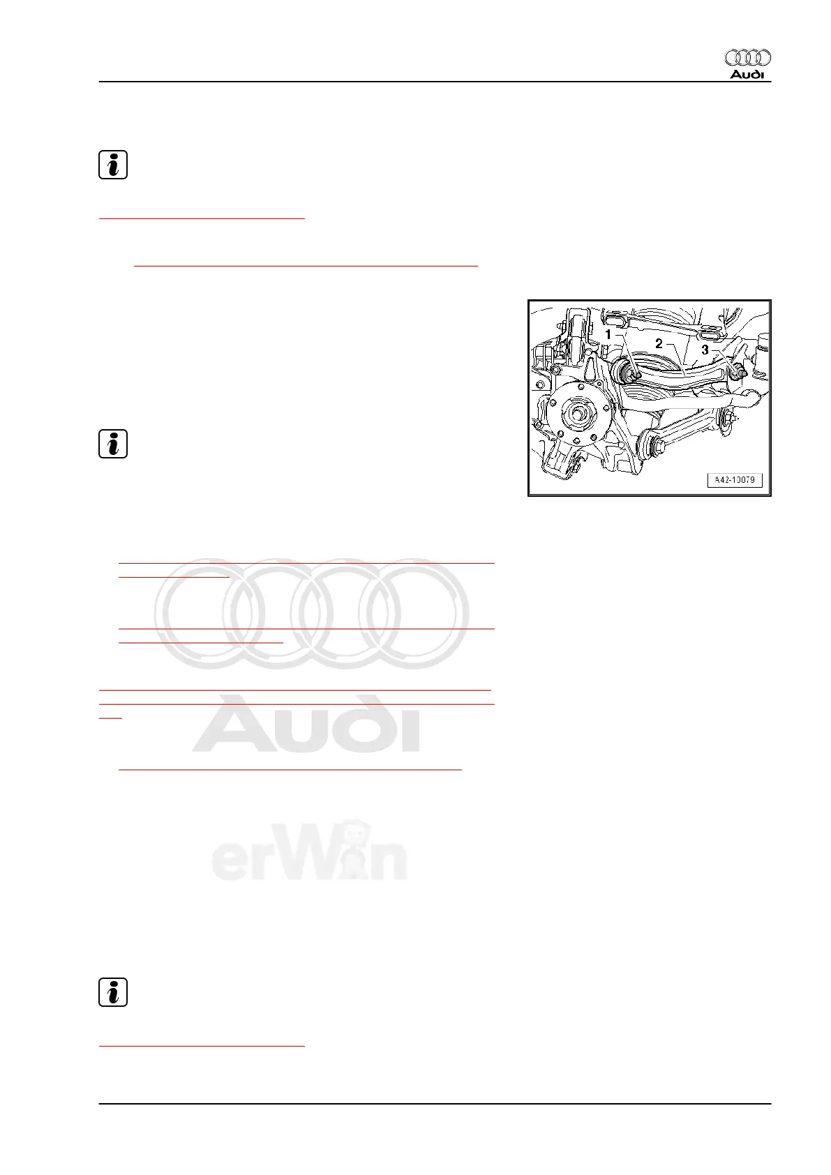
– Remove screw -1-.
– Remove nut -3- and remove screw.
– Remove rear upper control arm -2-.
Installing
Install in reverse order of removal. Note the following:
Note
♦
Bonded rubber bushings can only be turned to a limited extent.
Only tighten suspension screws when vehicle is in curb weight
or control position.
♦
Wheel bearing, lifting to curb weight position on vehicles with
coil springs, refer to
⇒ “1.4 Wheel Bearing in Curb Weight, Lifting Vehicles with Coil
Spring”, page 118 .
♦
For vehicles with air spring suspension, lift wheel suspension
in control position, refer to
⇒ “1.5 Wheel Bearing in Control Position, Lifting Vehicles with
Air Suspension”, page 120 .
Tightening specifications, refer to
⇒ “3.1 Lower Control Arm, Level Control System Sensor, Upper
Front and Upper Rear Control Arms and Tie Rod Overview”, page
138 .
– On vehicles with air suspension, position vehicle on wheels,
refer to
⇒ “4 Positioning Vehicle on Hoist and Wheels”, page 10 .
– Tighten the wheels, refer to ⇒ Rep. Gr. 44 .
– On vehicles with automatic headlamp range control system,
perform a basic setting on the headlamps, refer to ⇒ Rep. Gr.
94 .
3.6 Tie Rod, Removing and Installing
Special tools and workshop equipment required
♦ Torque Wrench 1332 40-200Nm - VAG1332-
Removing
Note
An axle alignment may be required. Refer to
⇒ “5 Wheel Alignment”, page 247 .
Audi Q7 2007 ➤
Suspension, Wheels, Steering - Edition 01.2014
3. Lower Control Arm, Level Control System Sensor, Upper Front and Upper Rear Control Arms and Tie Rod 143