Installation
Instruction handbook bmaXX 5000
Document No.: 5.09021.19
151
of 346
7
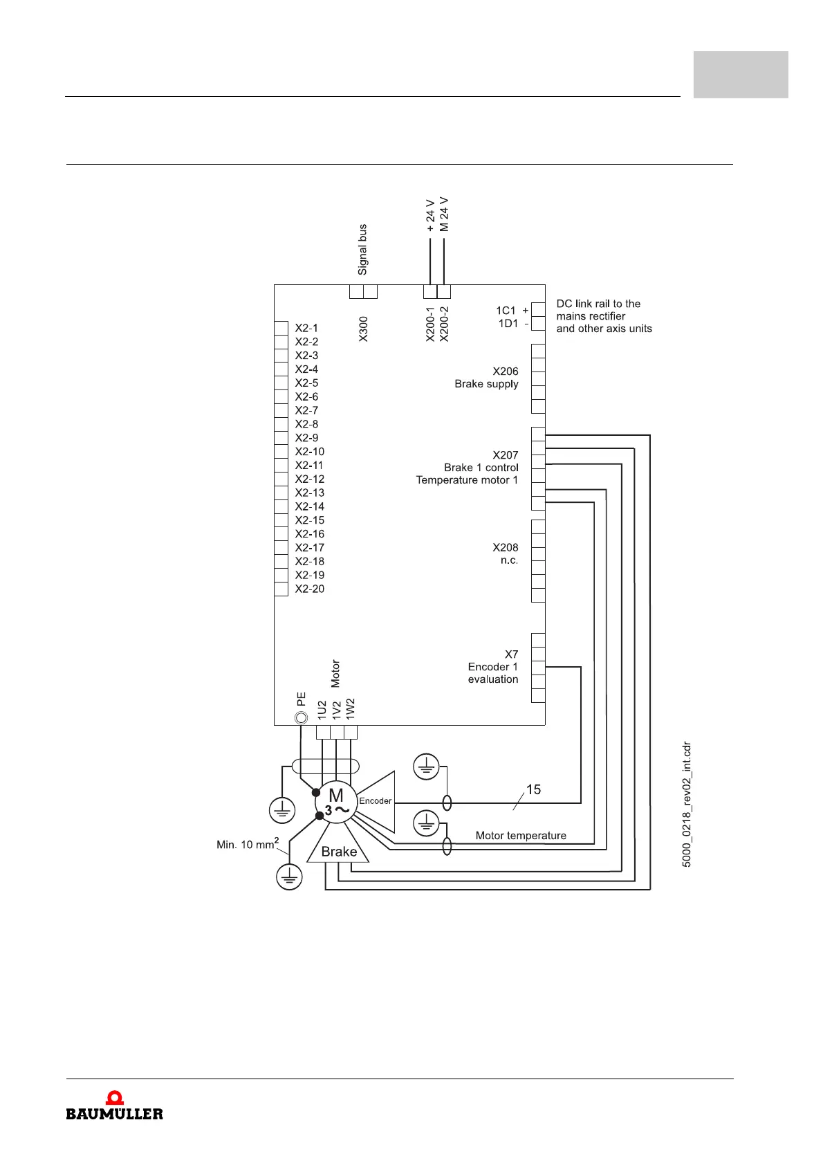
BM50XX-XX01 Normally closed contact expected on the inhibit input.
Figure 71: Connection diagram for the BM50XX-XX01 without safety function
NOTICE:
Connection for
external brake
resistor, only.
Do not connect
an additional
capacitance.
External brake
resistor
NOTE!
The use of a power choke (L1) is mandatory for the function of the mains rectifier unit.
An operation without power choke is not allowed.
1C1, 1D1 Connections for the DC link, see ZFigure 80– on page 164.
PE Power supply PE-connection
1U1, 1V1,
1W1
Power supply connection, see ZFigure 80– on page 164.
F1 Fuses (cable + device)
L1 Power choke
Z1 Line filter
K1 Main contactor (option)
X200 Connections for 24 V voltage supply; for additional information, see ZFigure 80– on page
164 (SELV/PELV).
X1 Control inputs and outputs, for additional information see ZFigure 80– on page 164 and
ZElectrical connections of the BM50XX-XX0X-... without safety function– on page 164.
X300 Signal bus
X101 Brake resistor