29
of 346
Instruction handbook bmaXX 5000
Document No.: 5.09021.19
3TECHNICAL DATA
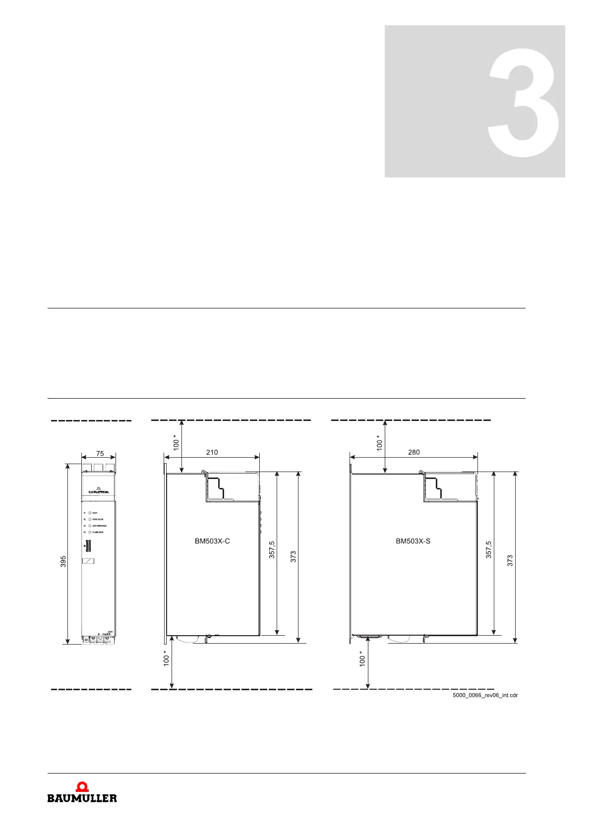
3.1 Dimensions
The following drawings show the main dimensions of the devices in millimeters [mm]. The
space requirements in the control cabinet are also determined based on these drawings.
To make the necessary drill holes/cutout sections, use the drawings in ZDrilling pattern–
as from page 117.
3.1.1 BM503X dimensions
Figure 3: BM503X-C/-S dimensions
*: Observe minimum clearance.
Please follow the notes for mounting and
ZCooling– on page 58.