Connection diagrams
Instruction handbook bmaXX 5000
Document No.: 5.09021.19 Baumüller Nürnberg GmbH
150
of 346
7.13
7.13 Connection diagrams
The connection diagrams are separated in connection diagrams for the electrical mains,
motor etc., Zpage 152– and the front side connections Zpage 179–.
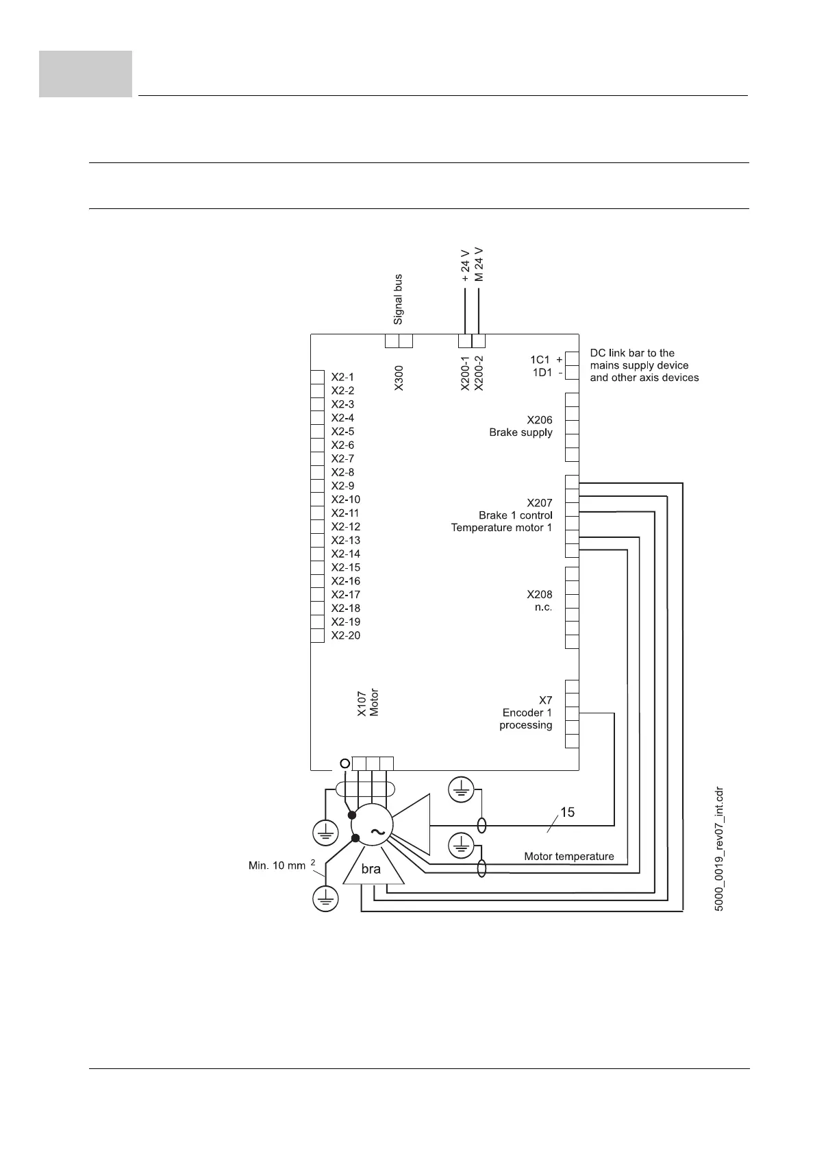
7.13.1 Connection diagram of BM50XX-XX0X-... mains rectifier without safety function
BM50XX-XX00 Normally open contact expected on the inhibit input.
Figure 70: Connection diagram for the BM50XX-XX00 without safety function
NOTE!
The identifiers 1C1 and 1D1 were taken over from DIN EN 60445. 1C1 is the connec-
tion to the positive DC link cable/bar, and in the past was identified by Baumüller in
some devices as ZK+. 1D1 is the connection to the negative DC link cable/bar, and
in the past was identified by Baumüller in some devices as ZK-.
NOTE!
Description of BM5030 with safety function BM5030-XX2X-...
see ZD.5 Connection diagram BM5030 with safety function– as from page 328.
NOTICE:
Connection for
external brake
resistor, only.
Do not connect
an additional
capacitance.
External brake
resistor