Accessories and spare parts
Instruction handbook bmaXX 5000
Document No.: 5.09021.19
259
of 346
11
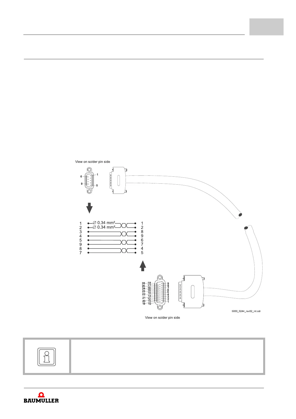
11.1.3 Hybrid cable device-encoder-motor
Selection The trailing cables are suitable for mobile deployment, for example in mobile cable han-
dlers. In addition, the cable sheath can be used in environments with acids and bases
(e.g. coolant).
The encoder wires for HIPERFACE DSL
®
encoders are connected with the device.
Cables pre-assembled - trailing type; CE UL/CSA, Halogen-free, Silicone-free, FCKW-free,
RoHS compliant, additional lengths upon request.
Length
Hybrid cable motor HIPERFACE DSL
®
15 A
speedtec
®
M23
20 A
speedtec
®
M23
21 A
speedtec
®
M40
28 A
speedtec
®
M40
36 A
speedtec
®
M40
Part No.
3 m 464201 464217 464235 464278 464294
5 m 464202 464218 464236 464279 464295
7 m 464203 464219 464237 464280 464296
10 m 464204 464220 464238 464281 464297
15 m 464205 464221 464239 464282 464298
20 m 464206 464222 464240 464283 464299
25 m 464207 464223 464241 464284 464300
30 m 464208 464224 464242 464285 464301
35 m 464209 464225 464243 464286 464302
40 m 464210 464226 464244 464287 464303
50 m 464211 464227 464245 464288 464304
60 m 464212 464228 464246 464289 464305