Display and operating elements
Instruction handbook bmaXX 5000
Document No.: 5.09021.19 Baumüller Nürnberg GmbH
96
of 346
4.4
4.4 Display and operating elements
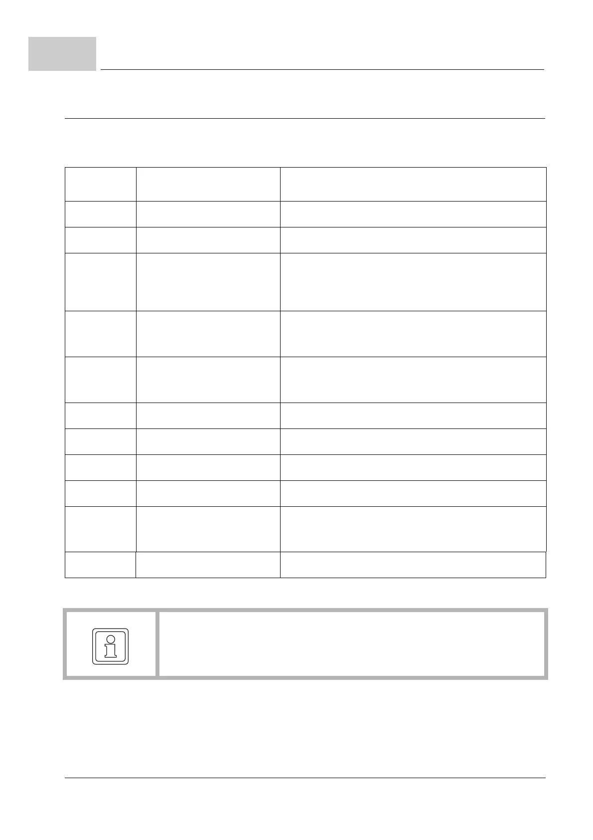
4.4.1 LED display BM50XX-XX0X-... without safety function
Figure 41: Display/operating elements BM50XX without safety function
NOTE!
Description of BM5030 with safety function BM5030-XX2X-...
refer to ZD.4 LED display BM5030 with safety function– as from page 326.
LED
H1
Mains rectifier unit ready-to-operate
green: Power supply and DC link voltage available,
internally OK
red: Power supply failure - automatically restart
when power supply returns.
blinking red: Power supply failure longer than 10 s - restart
after Power supply return has to be acknowl-
edged (X1:4).
Refer to ZError acknowledgment of BM50XX–
on page 254.
LED
H2 red: Phase failure
LED
H3 red: Over temperature
LED
H4 red: DC link error:
U
DC link
overvoltage or
U
DC link
overcurrent or
Inhibit input active