Identification of the device
Instruction handbook bmaXX 5000
Document No.: 5.09021.19 Baumüller Nürnberg GmbH
92
of 346
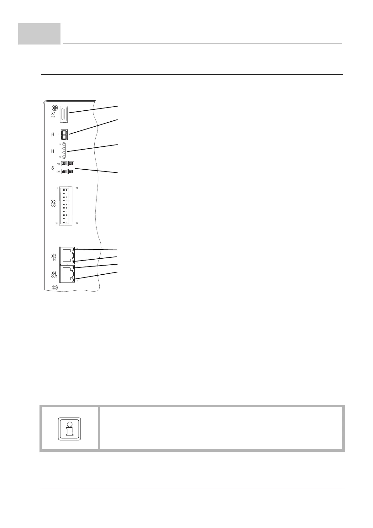
4.2
BM5XXX-XXXX-XXXX-XXXX-XX-XXXX Add-on module
00: Without module
01: With option module IEE with external supply
03: With option module SIE with internal supply
04: With option module SVP-001-001, 4 analog inputs (for voltage),
4 analog outputs (voltage)
05: With option module SVP-001-002, 4 analog inputs (2 for voltage,
2 for current), 4 analog outputs (voltage)
06: With option module SVP-001-003, 4 analog inputs (for current)
4 analog outputs (voltage)
07: With option module EIP-001-001 EthernetIP incl. IEE with external supply
08: With option module MOD-001-001 Modbus/TCP incl. IEE with external supply
BM5XXX-XXXX-XXXX-XXXX-XX-XXXX Fieldbus configuration
01: EtherCAT
®
CoE
02: VARAN
03: CANopen
®
04: POWERLINK
®
05: ProfiNET RT/IRT
07: EtherCAT
®
SoE
BM5XXX-XXXX-XXXX-XXXX-XX-XXXX Hardware configuration controller
See ZPage 93–.
BM5XXX-XXXX-XXXX-XXXX-XX-XXXX Version
00: Standard
01: PCB with protective lacquer
02: Special version for customer
03: PCB with protective lacquer, without accessories kit, without DC link rails
04: Without accessories kit, without DC link rails
05: Special version for customer
BM5XXX-XXXX-XXXX-XXXX-XX-XXXX Controller software version
NOTE!
Only devices with type code BM5XXX-XXXX-XX01/03 and -XX04/05/06 provide an
add-on module!
The add-on modules are built-in and cannot be changed.
It is forbidden to remove the yellow front cover.