Electrical data
Instruction handbook bmaXX 5000
Document No.: 5.09021.19 Baumüller Nürnberg GmbH
76
of 346
3.4
1)
All rated values are based on an power supply voltage of 400 V/50 Hz, a DC link voltage of 640 V, a control
voltage of 24 V and a surrounding temperature of 40 °C and the switching frequency specified.
2)
The input current must be reduced between 40 °C and 55 °C, refer to correction values at changed operation
conditions, ZCorrection values for the output current of the mains inverter BM50XX, BM51XX– on page 51.
3)
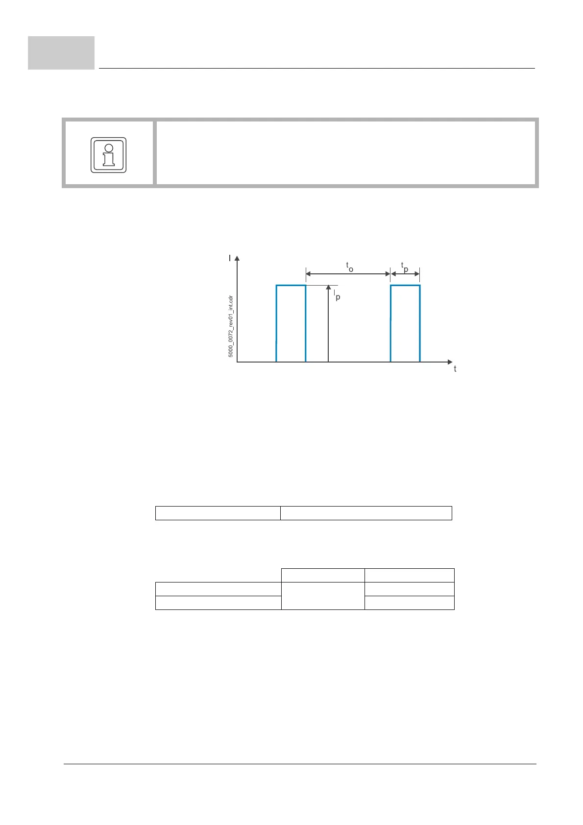
The output voltage is a pulsed direct voltage. The adjusting range is based on the RMS-value of the funda-
mental wave.
4)
The range of the output frequency is based on a stationary operation in the linear range of the PWM, i. e.
without overmodulation.
The quality of the generated output voltages depends on the ratio between output frequency and current con-
troller frequency f
I-R
(f
I-R
= 1/cycle time current controller).
The maximum output frequency f
max
, generated with high quality, is calculated as follows:
Furthermore the controller sets an upper limit for the output frequency of 599 Hz (please contact the respon-
sible Baumüller sales department, keyword: export restriction).
The range of the output frequency is defined as follows:
*)
900 Hz could be generated by the controller
The device is able to generate output voltages with frequencies between f
max
and 599 Hz and the controller
allows that, however the quality of this voltages cannot be guaranteed.
Typical the devices are marked with the max output frequency at 4 kHz switching frequency: 0 ... 450 kHz.
5)
The device draws the rated/peak current at rated supply voltage. The input current must be reduced if power
supply voltage is higher than 400 V and the DC link output power remains constant, refer to ZDerating: Out-
put current as function of the DC link voltage axis units– on page 57.
6)
The actual possible overload time depends on the preloading of the device and the heat sink temperature
and is detected by the overload monitoring of the device.
Assumption: initial conditions before the overload occurrence: heat sink temperature 40 °C, I = 0 A,
7)
Without loads on the digital outputs and motor brake.
8)
Short-circuit protected for a maximum of 1 minute.
9)
This power rating is the total power rating of both axes.
10)
120 s for BM53XX-SXXX
10 s for cold plate devices BM53XX-CXXX, refer to ZCooling– as from page 58
11)
The continuously permitted output current must be reduced complying with ZOutput frequency-dependent
current derating– on page 77 if the statical output frequency is lower than 15 Hz and the frequency remains
between 0 and 15 Hz for over 5 seconds.
12)
Max 6,4 A, when considering safe motor brake:
13)
Max. 4,0 A, when considering UL61800-5-1
PWM frequency Current controller cycle time Range of the output frequency
2 kHz 250 µs 0 - 225 Hz
4 kHz 125 µs 0 - 450 Hz
8 / 16 kHz 62.5 µs 0 - 599 Hz (900 Hz
*)
)
f
max
f
I-R
K
pf
--------
, typical K
Pf
18=