82.3-0000010 OM
105
If your tractor design uses a retaining rod to lock the upper link in the transport posi-
tion, the retaining rod can be mounted in two positions:
- retaining rod position for the working position of the upper link (Figure 4.3.14a));
- retaining rod position for transport position of the upper link (Figure 4.3.14b));
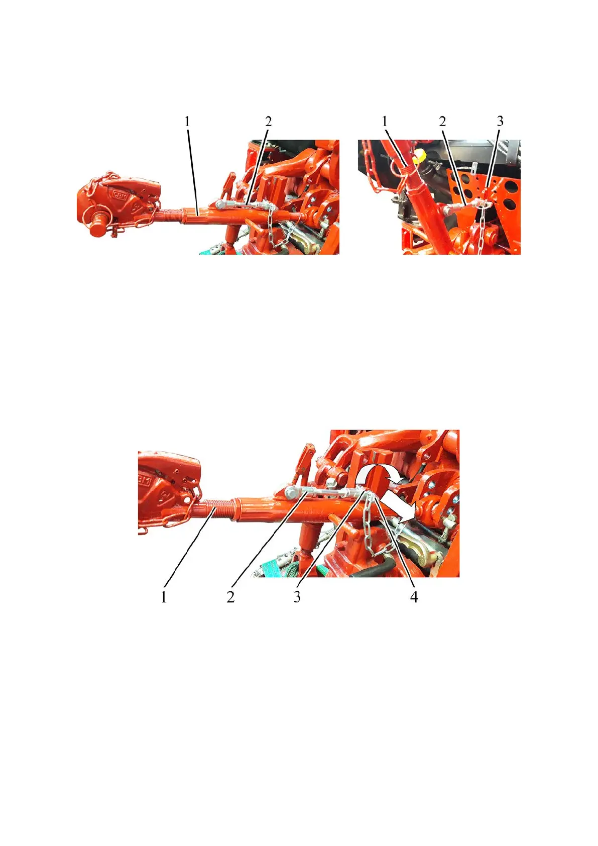
a) RLL working position b) RLL transport position
1 – upper link; 2 – retaining rod; 3 – HLL outlet bracket.
Figure 4.3.14 – Mounting positions of the retaining rod
When switching the RLL from the working position to the transport position, it is
necessary to fix the upper link 1 (Figure 4.3.14) in the transport position. This requires dis-
connecting the free end of the retaining rod 2 from the upper link 1 and connecting it to the
HLL output bracket 3.
To disconnect the free end of the retaining rod 2 (Figure 4.3.15) from the upper
link 1, do the following
- disconnect the upper link 1 from the agricultural machine;
- turn ring 3 clockwise by ≈180° (until a click is heard);
- remove the forelock key 2.
1 – upper link; 2 – retaining rod; 3 – ring; 4 – forelock key.
Figure 4.3.15 – disconnecting the free end of the retaining rod from the upper link
 Loading...


