82.3-0000010 OM
106
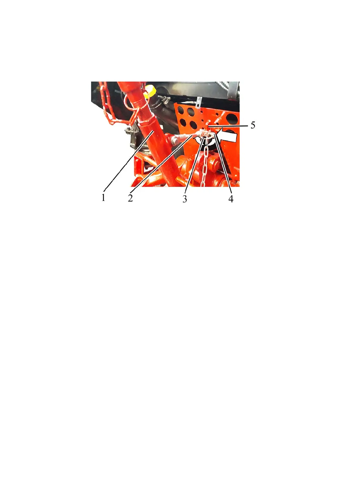
To connect the free end of the retaining rod 2 (Figure 4.3.16) to the HLL output
bracket, do the following:
- align the hole in the free end of the retaining rod 2 with the hole in the HLL output
bracket 5;
- insert the forelock key 4 in the aligned holes;
- turn the ring 3 clockwise by ≈180° (until a click is heard);
1 – upper link; 2 – retaining rod; 3 – ring; 4 – forelock key; 5 – HLL output
bracket.
Figure 4.3.16 – Connection free end of the retaining rod to the HLL output bracket
When switching the RLL from the transport position to the working position, it is
necessary to remove the upper link 1 from the transport position locking (Figure 4.3.14).
To do this, disconnect the free end of the retaining rod 2 from the HLL output bracket 3
and connect it to the upper link 1 according to the procedure specified above in the text.
When installing the RLL in transport position, if the lifting rods are connected to the
lower links through grooves C (Figures 4.3.7 and 4.3.8), they must be moved to the holes
A or B of the lifting rods yokes. Grooves of yokes B must be ahead of the holes if viewed in
direction of tractor travel.