82.3-0000010 OM
29
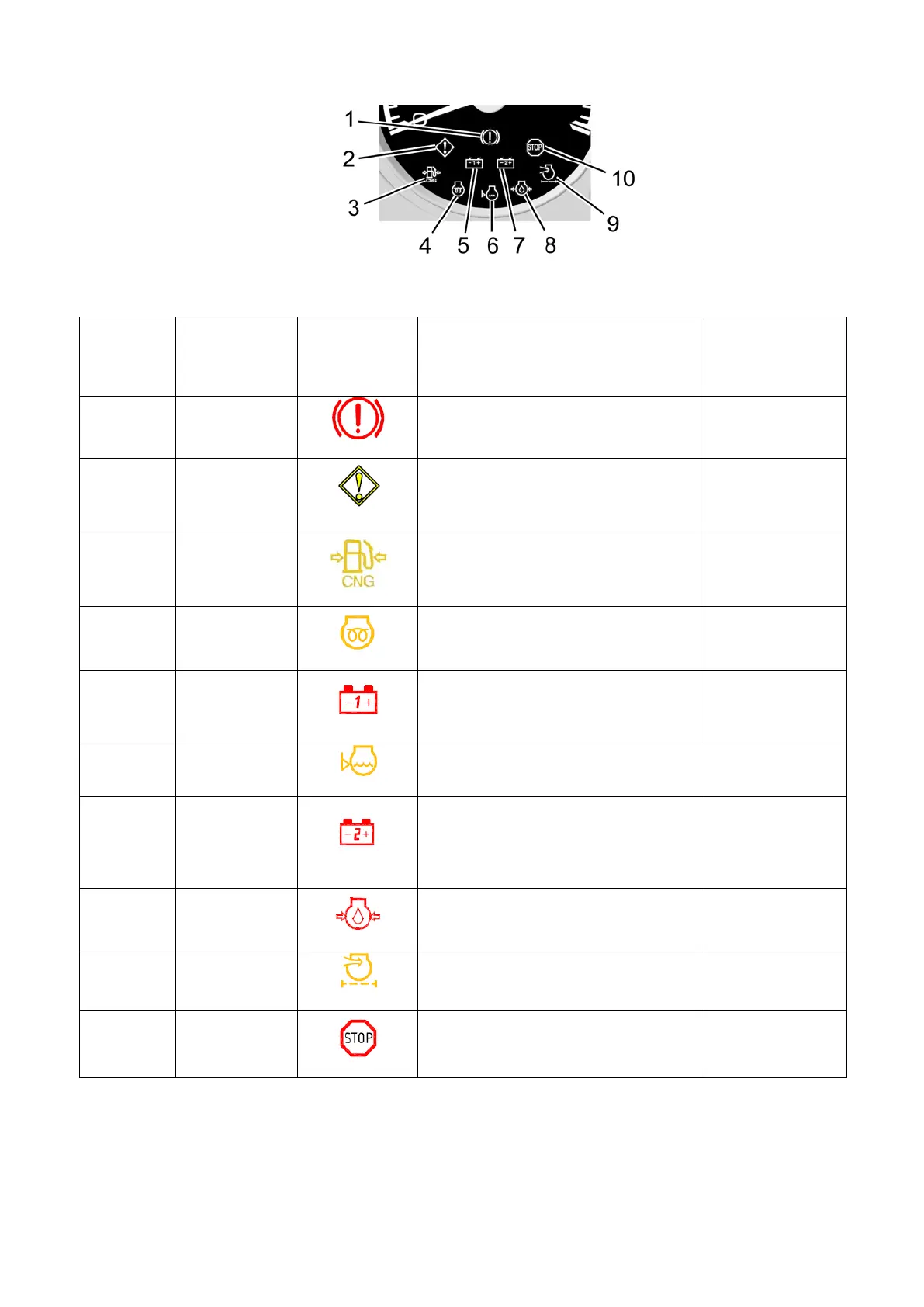
Figure 2.6.2 – Location of annunciators built in the engine crankshaft speed gauge
Table 2.6.1 – Assignment of annunciators built in the engine crankshaft speed gauge
according
to Figure
Annunciator
name
Symbol/
color
Assignment
tion / possibility
of deactivating
the buzzer
1
Brake system
failure
Not in use
–
2
Non-critical
failure
Orange
Lights up when there is a failure
together with other annunciators to
draw the operator’s attention,
it is
required to eliminate the failures.
Available /
available
3
Low gas
pressure
Not in use
–
4
Heating plugs
Lights
plugs.
–
5
Alternator
operation
Red
AB on/off indicator when starter
and instrument switch is in position
“0”.
Failure of alternator, battery
charge missing.
Available /
available
6
Low coolant
volume
Not in use
–
7
second bat-
tery (VC op-
eration test-
Red
Not in use
–
8
oil pressure
in the engine
Immediate engine stop and failure
elimination are required.
Available /
not available
9
Air cleaner
filter clogged
Maximum permissible filter dirti-
ness level is exceeded, the filter
Available /
available
10
Critical failure
Immediate engine stop and failure
elimination are required.
Available /
not available