82.3-0000010 OM
95
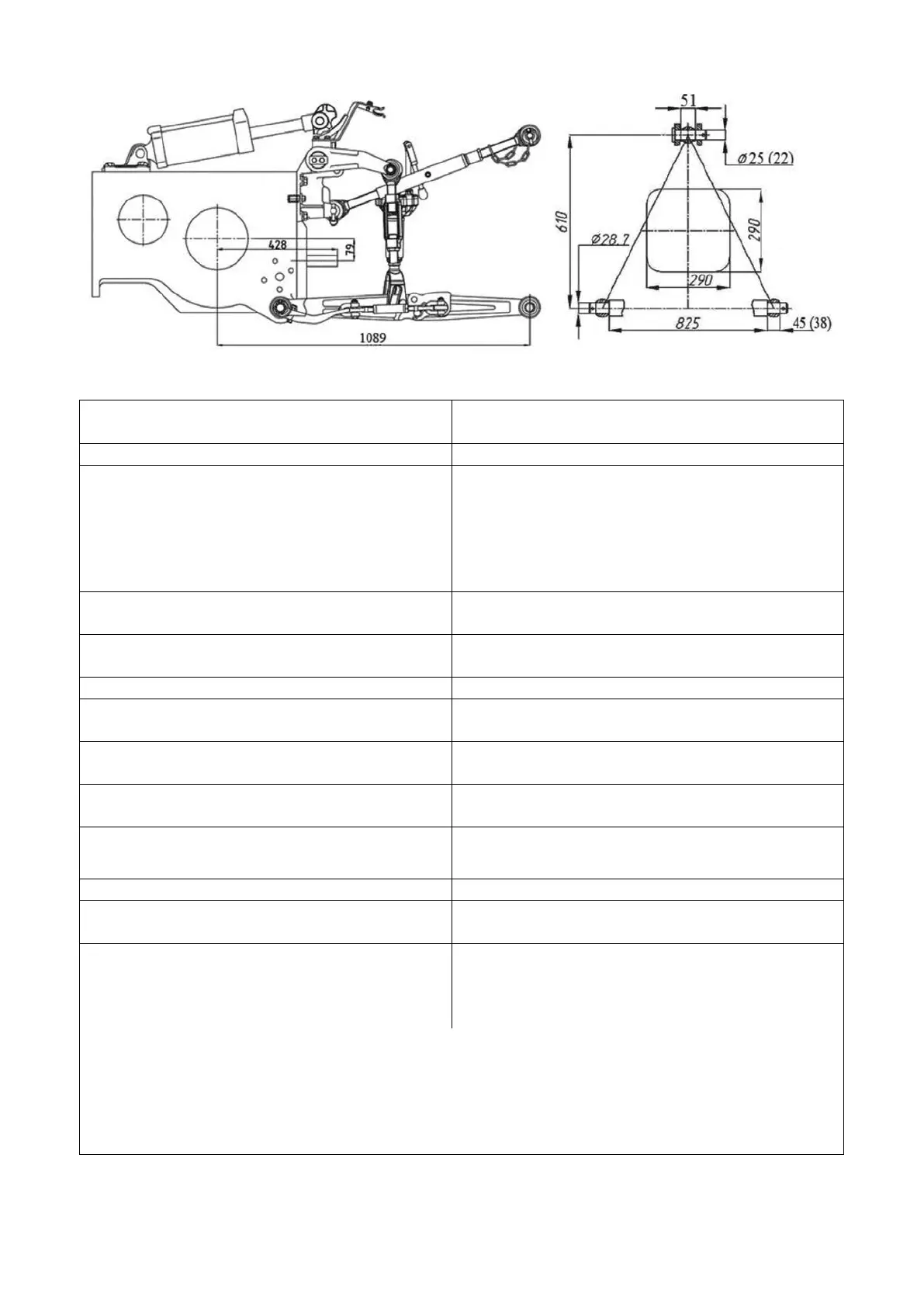
Figure 4.3.1 – Rear lift linkage diagramm of “NU-2” type
Table 4.3.1 – Basic parameters and coupling dimensions of RLL
Standard size (configuration)
of the device
1 Category (acc. to ISO 730-1)
Device consisting of three links (one upper
and two lower links) connected with the trac-
tor by joints
; free ends of links with hinge
joints
are coupled during implement coupling
with the connecting elements of the imple-
For connecting (mounting) and coupling of
mounted, semi-mounted implements
Split with hinges (optional: telescopic with
hinges or clamps, solid with hinges or clamps)
5 Length of lower links, mm
6 Hinged joint width of the upper (lower)
link, mm
51 (45) acc.to ISO 730-1
51 (38) acc.to GOST10677
7 Diameter of pin of rear-end hinged joint
of the upper link, mm
25 acc.to ISO 730-1
22 acc.to GOST 10677
8 Diameter of holes in rear hinge joints of
lower links, mm
28.7
9 Distance between PTO shaft end exten-
sion face and suspension axis, mm
661
11 Length of the suspension axis along the
shoulders
1)
825
12 Lifting capacity of the device, kN
2)
:
а) on the suspension axis;
b) at overhang of 610 mm from the sus-
30
18
________________________________________________________________________
__________________________________________________
1)
Dimension refers to the implement coupled.
2)
It is not allowed to give RLL load exceeding the
load of tires specified by loading
instructions set forth in subsection 3.2.8 ”Selection of optimal inner pressure in tires depending
on operational conditions and load on tractor axles, instructions for use of tires”.