38477BA2B
2 – 160 25.5.09
2 Installation Volume 2
2.5 Mounting the Shielding
Shielding, source type, isotope and activity for each measurement
configuration will be selected together with the customer to ensure
compliance with the locally permitted dose rate limits. Co-60 or
Cs-137 point sources are used which are tightly welded into a
sturdy stainless steel capsule. Therefore, no radioactive material
can escape, provided the source is intact, and contaminations are
ruled out.
For point source shieldings, the capsule with the source is fixed on
a source holder and installed in the shielding. For rod source shield-
ings, a rod source is placed into the existing borehole of the shield-
ing. The shielding matches the length of the source.
The distance from the source shieldings to the vessel surface is
designed such that reaching into the beam path with the hand is
prevented (reference value approx. 20mm). For shieldings with a
rotary cylinder (vertically standing cylinder) make sure that the
cylinder can be rotated on the vessel surface without friction.
Apart from a few exceptions, all shieldings are filled with lead to
keep the dose rate on the surface of small construction sizes as low
as possible. Therefore, the shielding are quite heavy. The weights
are listed in the technical drawings in chapter "6 Technical Draw-
ings" on page 2–251.
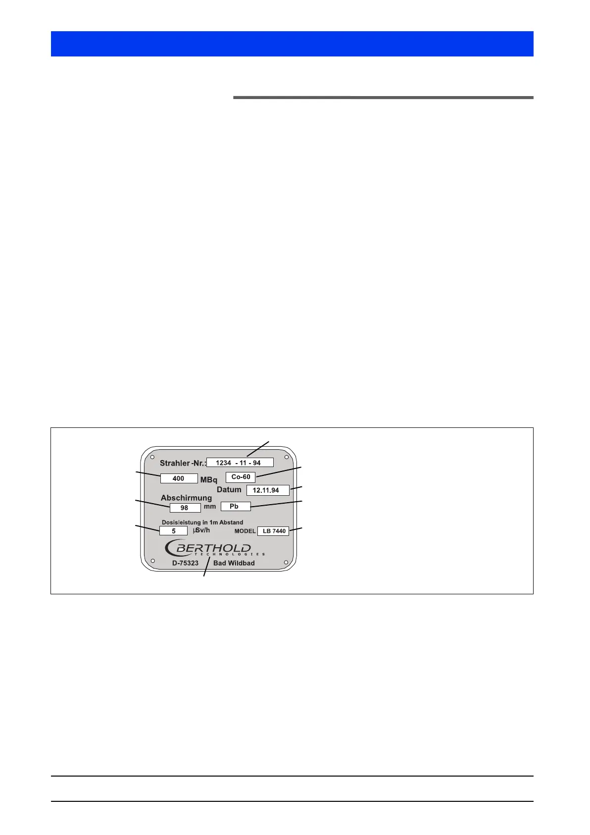
For information on the design of source and shielding please refer
to the technical documentation and the identity plate (Figure
2-17).
Figure 2-17 Identity plate
Please observe the safety instructions in Volume 2, Uni-Probe
Installation, on page 1–27 for installation. A source may be trans-
ported only in its shielding. Keep the source shielding closed during
storage, transportation and installation.
The arrangement is fixed during the planning stage and entered in
a drawing or defined in writing. These details must be observed
carefully to ensure correct linearization data. For detailed informa-
tion on the construction and function of the shieldings, see the
drawings that are part of the documentation.
1
2
3
4
5
6
7
8
9
1 Source number
2 Isotope
3 Source manufacturing date
4 Shielding material
5 Type of shielding
6 Manufacturer of shielding
7 Dose rate in 1m distance
8 Effective shielding thickness
9 Activity


 To Next Page