38477BA2B
3 – 332 25.5.09
Menu Structure Volume 3
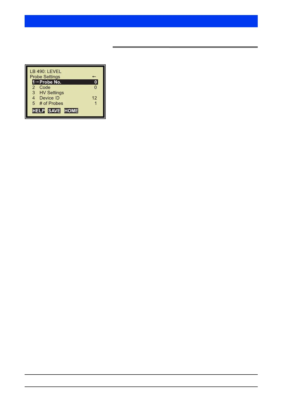
2.37 PROBE SETTINGS
1 PROBE NO.
Select the number of the detector you want to indicate or set up. If
the system comprises one detector you have to enter 0.
If Auxiliary Units are connected, then the probe settings of the Aux-
iliary Units with number 1, 2,... may also be displayed or set up
(see also Multi-Detector Mode on page 2–121).
2 CODE
Select the probe code for the automatic HV-control. The currently
set detector code is also displayed in this window.
The probe code is set by BERTHOLD TECHNOLOGIES. It is depen-
dent on the scintillator size, see Volume 2, section "1.6 Detector
Codes", on page 2–133.
3 HV SETTINGS
Shows the HV settings. Check and change the HV setting of the
probe.
4 DEVICE ID
With one Main Unit:
• Probe No. 0: Shows the Device ID.
• Probe No. 1 … 7:
Enter the Device ID of the connected Auxiliary Unit to assign an
Auxiliary Unit to the
PROBE NO. (detector number).
With one Auxiliary Unit:
• Detector code 0: Shows the Device ID.
Explanations
The Device ID is the device number of the Uni-Probe. Each Uni-
Probe has a different device number. You find the white label with
the device number at two different locations in/on the Uni-Probe.
• outside on the Uni-Probe housing
• on the digital board below the strip terminal with terminals 51
... 60.
A two, three or four-digit number is printed on the white label. The
inscription reads: Dev. ID. XXXX.
The Device ID may also be queried, as described above, with the
setting Probe No. "0". For this purpose, the HART
®
Communicator
has to be connected to the respective device.


 To Next Page