Uni-Probe LB 490
BERTHOLD TECHNOLOGIES GmbH & Co. KG
3 – 327
Volume 3 Menu Structure
3
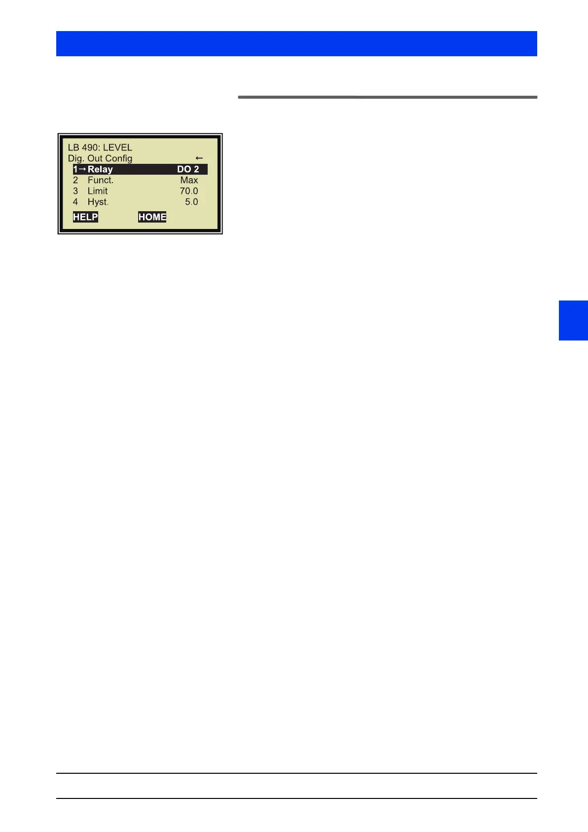
2.30 DIGITAL OUT CONFIG
1 RELAY
Select the relay you want to set up. Three relays (DO2, DO3; DO4)
can be set up. The relay DO 1 has a fixed setting as a failure relay.
2 FUNCT.
Define the function of the alarm relay. The following functions can
be selected:
•halted:
The relay indicates alarm when the Uni-Probe is in the Halt
mode. The error relay does not indicate an alarm in the Halt
mode, but in case of error.
• rad. interference: Radiation Interference
•Probe Temperature:
Probe Temperature: The relay triggers an alarm as soon as the
entered temperature limit has been exceeded.
• Min:
The relay triggers an alarm if the level remains below the
entered limit.
• Max:
The relay triggers an alarm if the level has exceeded the
entered limit.
• Unused: The relay does not trigger an alarm.
3 LIMIT
Enter the limit value (threshold) for the relay to trigger an alarm.
4 HYST.
Enter the hysteresis for the respective relay.
Example Setting: Max. relay; forward break-over point: 60%; Hyst. 5%
If the level exceeds 60%, the relay is set to the alarm status.
If the level then drops again below 55%, the relay is set back to
“Normal”.


 To Next Page