Uni-Probe LB 490
BERTHOLD TECHNOLOGIES GmbH & Co. KG
2 – 189
Volume 2 3 Electrical Installation
2
3.3 Switch Setting
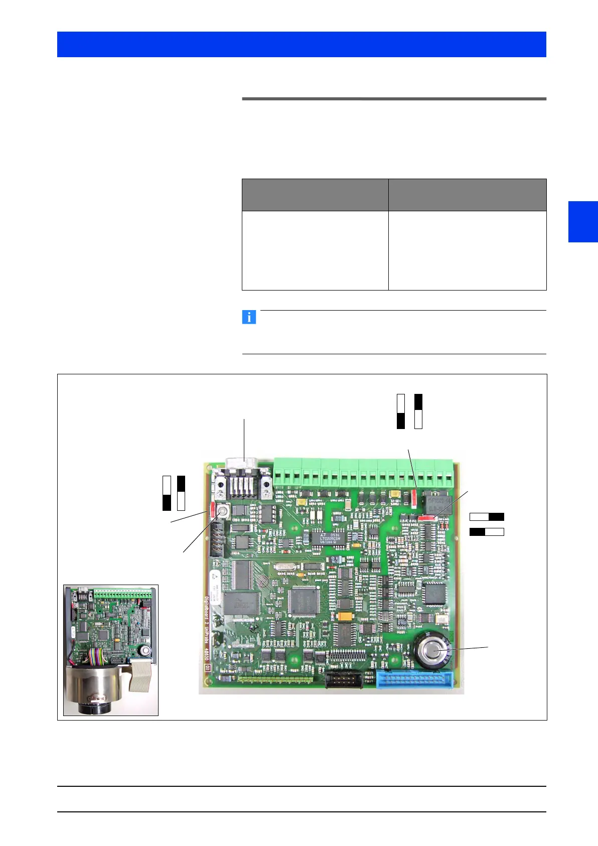
Select the operating mode for the current output and the load
resistance for the Auxiliary Unit via switches on the digital board.
Source / Sink mode Select the operating mode for the current output.
For safe HART
®
communication you need an impedance of at least
250
Ω
at the current output.
Figure 3-3 Digital board
Source-Mode
(Active current output)
Sink-Mode
(Passive current output)
The Uni-Probe will power the cur-
rent loop
Max. impedance: 500Ω
Min. impedance 120Ω
An external power supply has to
power the loop (factory setting).
Min. impedance 120Ω
Max. 24V
DC
/ Min. 12 V
DC
Max. impedance at 12V: 250Ω
Max. impedance at 24V: 500Ω
6
4
5
3
2
1
active
passive
120 Ohm / RS-485
4–20mA
ON OFF
Communication
HART fixed setting
autom. identification
with complete electronics


 To Next Page