Uni-Probe LB 490
BERTHOLD TECHNOLOGIES GmbH & Co. KG
2 – 191
Volume 2 3 Electrical Installation
2
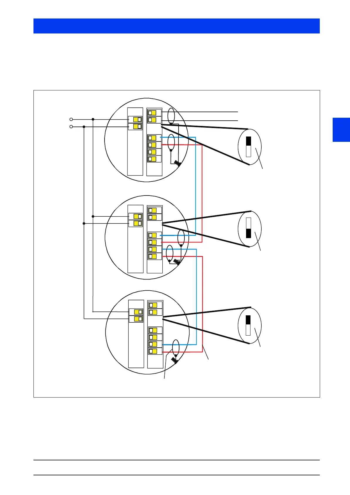
Multi-detector mode wiring Only a screened cable with twisted wires may be used as cable for
the RS485, e.g. the BERTHOLD TECHNOLOGIES cable, ID no.
32024. Connect the cable screen on both sides to the grounding
bolt.
Figure 3-4 Wiring diagram Main / Auxiliary Units
51
52
57
58
59
60
51
52
57
58
59
60
51
52
57
58
59
60
2
3
2
3
2
3
Power supply
Main Unit
Auxiliary
Unit 1
Auxiliary
Unit 2
RS -485
RS -485
Termination of last
auxiliary unit with
120 Ω by jumper.
Connect the cable screen on
both sides to the grounding bolt.
Use only cable with twisted
wires, e.g. Berthold
ID no.32024
Termination of Main
Unit with 120Ω by
jumper.
4–20mA Hart Signal
(screened cable recom-
mended)
In all Uni-Probes located
between the Main Unit and the
last Auxiliary Unit, the 120 Ω
resistor has to be turned off.