Uni-Probe LB 490
BERTHOLD TECHNOLOGIES GmbH & Co. KG
2 – 223
Volume 2 4 Repair, Maintenance and Service
2
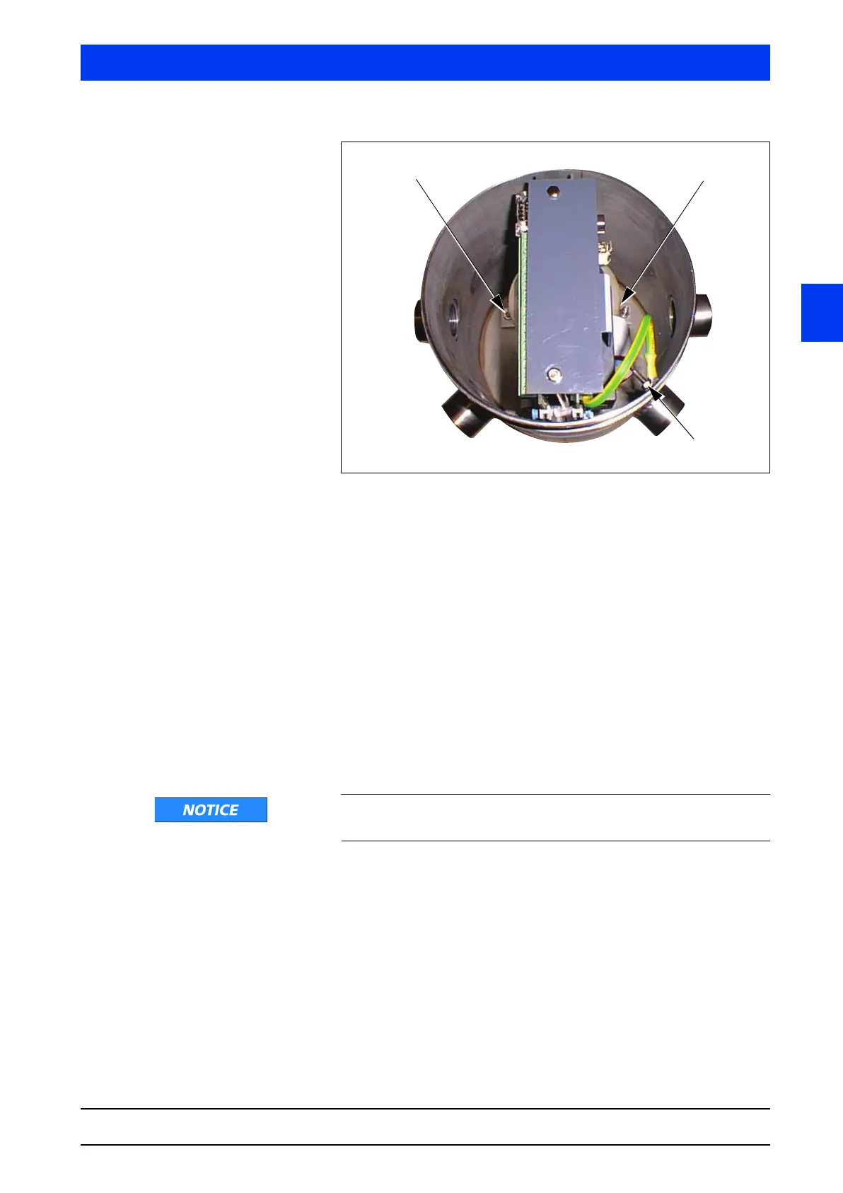
Figure 4-2 Dismantling the detector electronics
Carefully pull out electronics module horizontally together with
the crystal-multiplier assembly.
4.6.2 Installing the Electronics Module
Reassemble the electronics module in reverse order:
Carefully insert electronics module with the crystal-multiplier
assembly again into the housing.
Fix electronics fixture with the two nuts (M8). Tighten screws
evenly and alternating between screws.
Attach grounding cable to grounding screw with screws.
Close the housing carefully with the housing cover. Screw the
housing cover completely onto the housing and pull it tight
using a torque of 25Nm (reference value).
Before closing, make sure that the threads are clean and greased
with OKS 217.
If you have installed a new electronics module:
Remove the device numbers on the Uni-Probe and in the elec-
tronics housing and replace them by the new numbers sup-
plied.
You find the device numbers on white labels with a two, three
or four-digit number. The inscription reads: “Dev. ID XXXX”.
Establish the power supply to the Uni-Probe again.


 To Next Page