38477BA2B
2 – 280 25.5.09
6 Technical Drawings Volume 2
Slightly grease the housing cover in the shaft duct with MoS
2
grease, attach the cover and tighten the cover screws.
Correction of the switching points
for drives with pre-assembled
limit-switch box
Direct installation
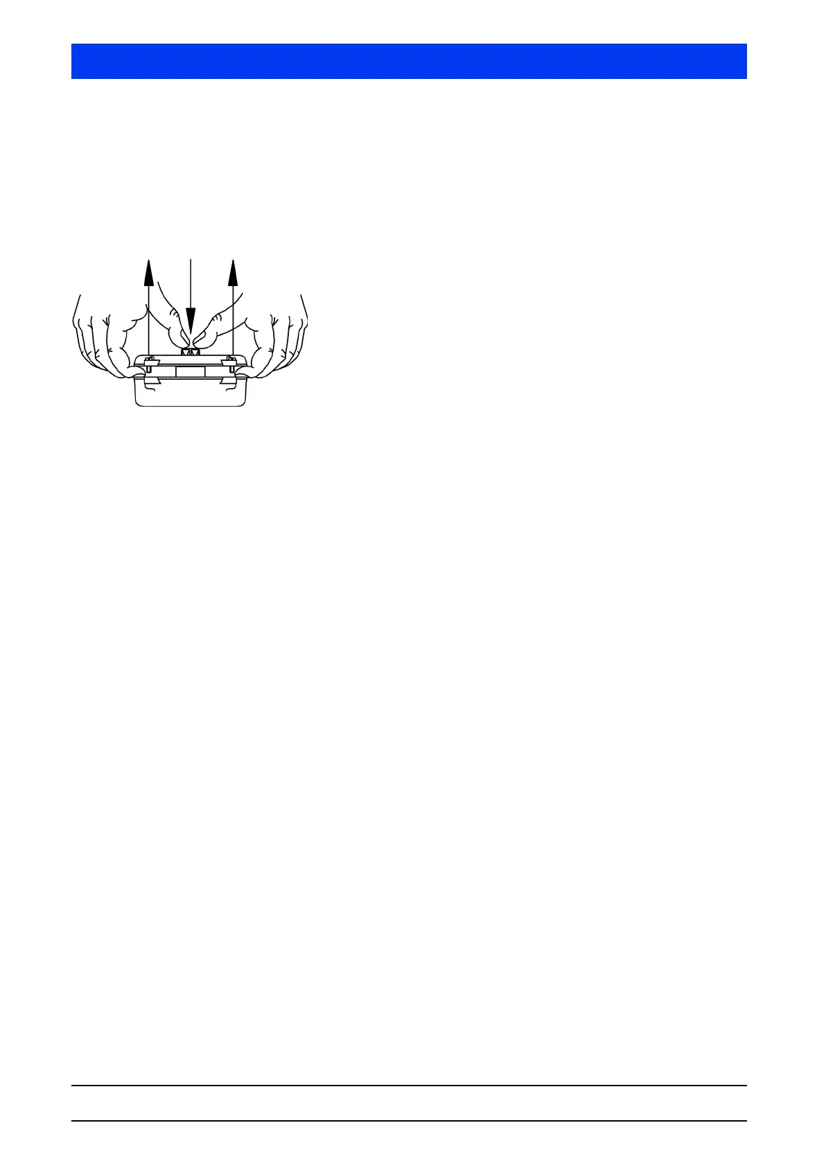
Unscrew the cover of the supplied limit-switch box and pull it
off, as shown in the illustration, while pushing down the
limit-switch shaft. Caution: Do not lose the cover sealing!
Remove shaft mounting bracket by opening the screws and
take off the limit-switch shaft.
Apply LOCTITE (or a similar adhesive) on mounting thread, put
on the supplied cork sealing and attach the bottom part of the
limit-switch box. Fix it using the screws supplied.
The two trip cams on the limit-switch shaft are fixed by one
screw each. Untighten these screws.
For more information please see "Adjusting the trip cams" on
page 2–277 and "Technical Specification / Electrical Wiring", on
page 2–278.
 Loading...
