38477BA2B
5 – 474 25.5.09
4 Menu Overview Volume 5
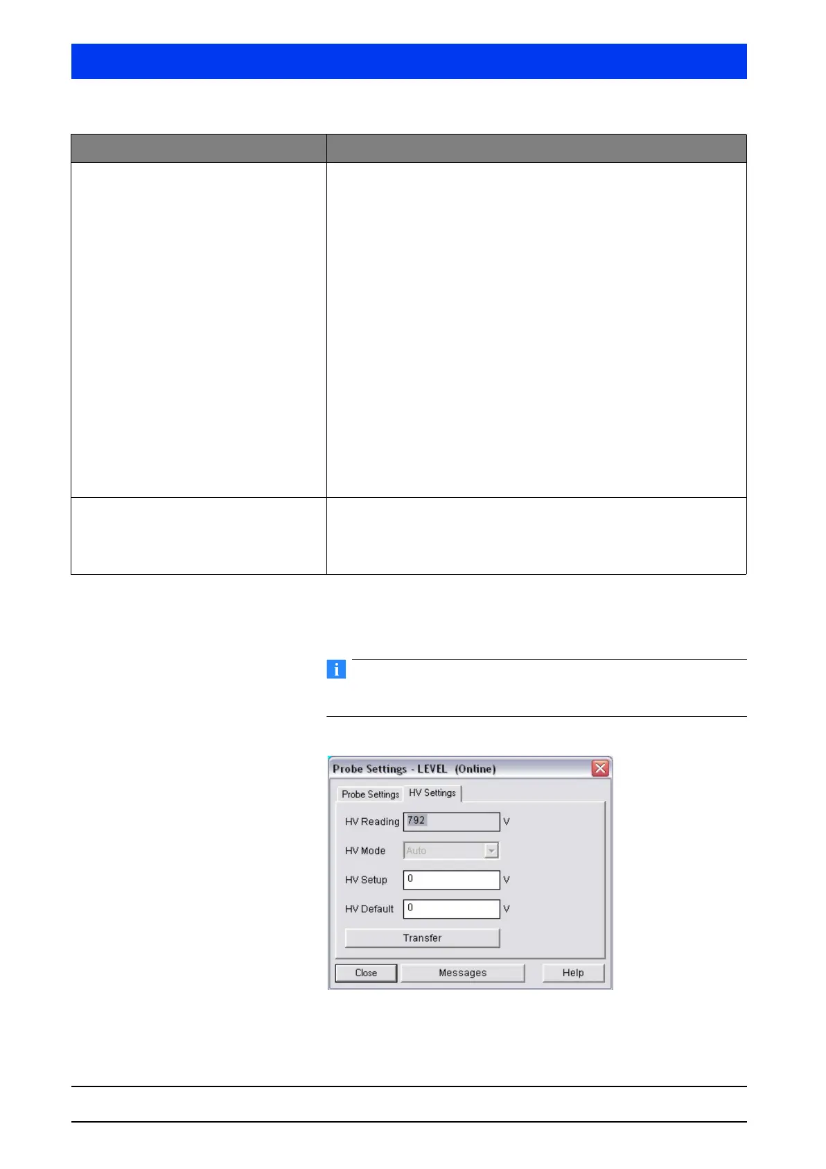
Enter the parameters in the text boxes of the PROBE SETTINGS
dialog box and click
TRANSFER to upload the setting to the
Uni-Probe.
Parameter changes in this online dialog become effective immedi-
ately (no upload to the device required).
HV SETTINGS Tab
Device ID With one Main Unit:
– Device ID 0:
Shows the Device ID.
– Device ID 1
… 7:
Enter the Device ID of the connected Auxiliary Unit to assign an Aux-
iliary Unit to the detector number.
With one Auxiliary Unit:
– Detector code 0:
Shows the Device ID.
Explanation:
The device ID is the device number of the Uni-Probe. Each Uni-Probe has
a different device number. You find the white label with the device num-
ber at two different locations in/on the Uni-Probe.
– outside on the Uni-Probe housing
– on the digital board below the strip terminal with terminals 51 ... 60.
A two, three or four-digit number is printed on the white label. The
inscription reads: Dev. ID. XXXX.
The device ID can also be queried, as described above, with the setting
detector number 0. For this purpose, the HART
®
Communicator has to be
connected to the respective device.
Number of Probes Total number of Uni-Probes used in the measuring system.
Example:
If one Main Unit and two Auxiliary Units are connected, you have to enter
the number of detectors = 3.
Parameters Description
 Loading...
